And... a simple practical measurement on the collector voltage is enough—if it drops close to zero, it’s OK. And, if possible, isolate the logic section GND from the 24V section GND.
1 Like
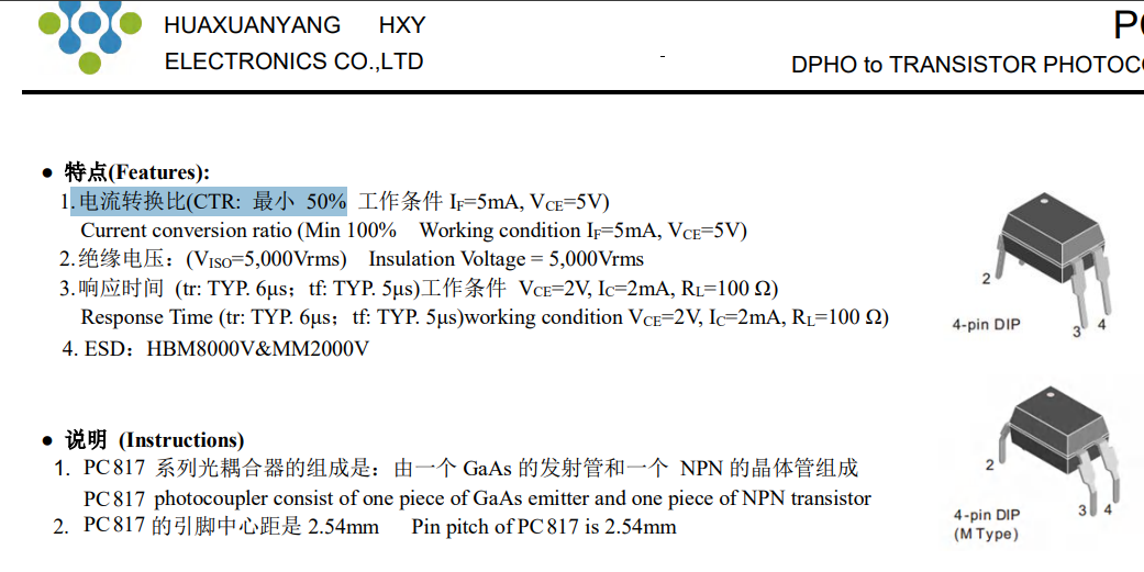
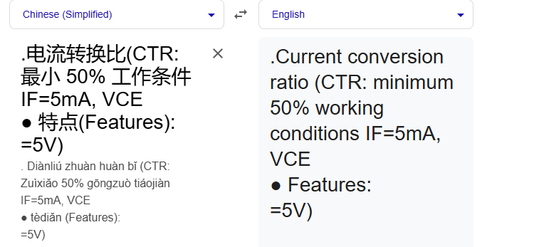
Kmin datasheet said in worst case CTR ratio is 50% minimum guaranteed CTR is 50% which they tested at 5V .CTR can be more than 50% but we should consider 50% in designing purpose

So what would be the point of different models A...D?
Anyway, like @Claudio_FF suggested, measure the collector voltage. If it's close to zero (few hundred millivolts), your LED current is sufficient.
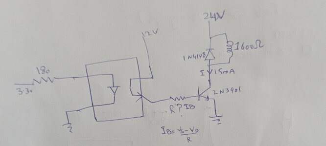
Yes, it works, but the LDO isn't necessary. It's enough to move the emitter resistor connected to GND to the right of the horizontal resistor. Two 2200 or 3300 Ω resistors will do fine.


It's just about acceptable, but if possible, choose one with a VDS of at least 40V
I have the impression that this is a project that should be worked out theoretically first ![]()
The idea of driving high resistance relay coil just with optocoupler was interesting.. ![]()
If that's not the point here, common relay modules use transistor, often together with optocoupler. No need to reinvent a wheel...

@jim-p
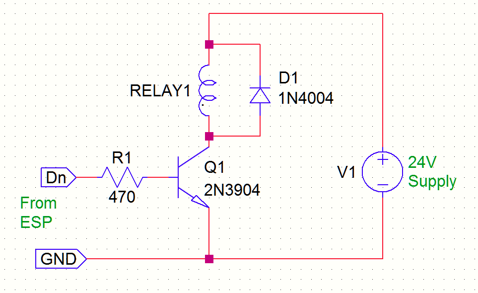
If I go with this circuit, please tell me how to select the resistor value at the base of the transistor.
I am trying to find out, but I don't seem to be correct.

Which optoisolator are you using?
pc817C
You need to use a smaller current like 10mA
So (12-0.7-0.2)/0.010 = 1110.
1.0K ohms would be good
The 0.2V is the optoisolator saturation voltage.
Why not use the circuit I show in post #33
1 Like
+1
As in post#10.
OP is over-thinking things with the opto coupler.
Leo..
AQY282eh costs $2.80, while its alternative SUPSiC GAQY212GH is $0.81. Both prices are expensive compared to PC817 at $0.029 and 2N3904S at $0.01. Adding four circuits to a board significantly increases the cost.
Uh, right, sorry, my mistake, I missed that last curl... ![]()
You did not mention cost before.
If there is no reason to isolate the 24V then use the circuit in post #29, it's the cheapest.
1 Like