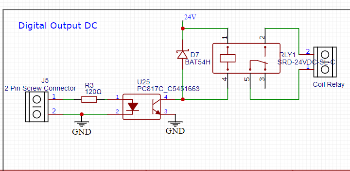
Please review my circuit. I am driving a relay with an ESP32. My concern is the unexpected high voltage that comes through the coil when it is de-energized. I have placed a flyback diode; my question is whether I placed the flyback diode correctly or not.
When I type your question into google I get the following
how do I place a flyback diode across a relay coil
connect it in parallel with the coil, with the cathode (the end with a band or a shorter lead) connected to the coil's positive terminal and the anode (the other end) connected to the coil's negative terminal
After just a quick look, it looks like the right polarity, but why a zener?
R3 could be higher. 28mA is above recommended current draw(/sink) of esp32 and also above PC817 design current. 180R would fit better.

The flyback diode is a good choice. Here is why: BAT54H is a fast switching, low forward voltage diode in a miniature surface mount package. It is designed for circuit protection, voltage clamping and portable applications.
The relay will not work correctly as you are not driving the opto coupler hard enough. You will need something in the 110 Ohm range. That will then require you to supply about 30 mA on J5, way more then the Arduino can supply.
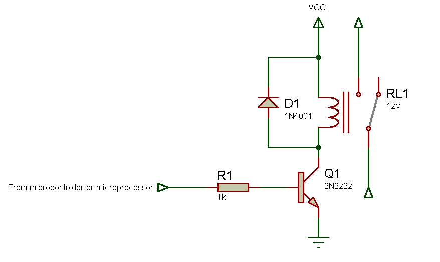
Add a transistor or MOSFET to drive the relay. Here is a circuit.

Yes, it's the best option, but with 24 V there's too much voltage on the gate. A 12 V zener diode should be added in series with the collector of the optoisolator. Alternatively, the emitter resistor could be moved to the gate to create a voltage divider.
Do you mind to open that little bit for learning purpose?
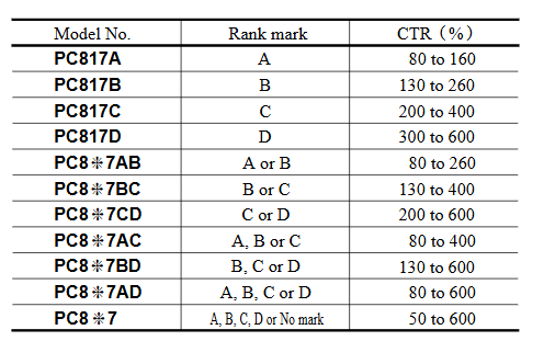
I'm not able to understand the datasheet, especially for the CTR of different PC817 models (like 817A vs 817C)
Two datasheets: one for the optoisolator and one for the relay. The coil of the indicated relay draws about 15 mA, which must flow through the transistor’s collector. The CTR helps to understand at least how much current must flow through the LED. In the worst case, the PC817 has a CTR of 50%, meaning that to have 15 mA flowing in the transistor, 30 mA are needed in the LED. It could require less if the CTR were higher, but the manufacturer guarantees it’s at least 50%. That said, a resistor should be chosen so that 30 mA flows through the LED (which is still too much for the poor ESP). The solution with the MOSFET (a common 2N7000 is perfect) is the best because from the transistor you can draw very little current, even just a few mA.
A common 1N4004 switches on equally fast than a Schottky diode.
Only switch-off times differ, which is irrelevant here.
A1N4148 would be my choice here.
I would only use a Schottky diode when a mosfet with PWM was involved, not for a relay.
Why the opto.
A simple NPN BJT transistor with base resistor will do.
Leo..

That is what the Op chose and per the BAT data sheet it is a recommended application.
The graphs show average curves that give an idea of the typical behavior of the values. The table indicates the minimum guaranteed CTR (typically with IF = 5 mA, VCE = 5 V, at room temperature) for that selection (A, B, C, etc.) of components (worst case: 200 for PC817C).
In practice, I would perform a simple measurement: I supply 10 mA to the LED, connect a 220 Ω resistor to the collector (powering it with 5V), and see if the collector voltage drops almost to zero. I then reduce the resistor until the collector voltage can no longer drop. From the ratio between the two currents, I get the actual CTR of that component under those operating conditions. In this case, with a PC817C and only 10 mA through the LED, you should be able to drive that relay (24V 15mA).
I chose an optocoupler to isolate my ESP32 from the high-voltage relay coil.
The 24V coil voltage itself is not a problem, but connecting two different power sources could be (conducted noise might be introduced). Therefore, using an optoisolator is still a good idea if it allows keeping the different power supplies isolated from each other.
but my relay coil resistance is 1600ohm to calculate current (I=V/R )15mA=24/1600, According to CTR 50% my optocoupler LED should have 30mA current which i can't give with esp32 ( Note: i am replacing 120 ohm with 180 ohm at Anode of Opto and 1n4148 as fly back diode in place of Schottky diode bat54)
OK, with 180 Ω you have about 11 mA on the LED:
(3.3-1.3)/180
Which model of optocoupler do you have? 817A? 817B? 817C?

pc817C
That was my question about the data sheet.
817C should have CTR 200-400%.
So with 15mA through LED you should be ok for the 15mA coil draws.