Hi,
I'm trying to write a code for simple progress bar (0-90 degrees) that uses tft.fillCircle
Basically a circle that sweeps from 0-90.
I have used a math formula for calculating the X,Y of the center of circle.
-That part works ( it sweeps from 0- to 90)
I'm also using analog input from Potentiometer to test it.
Now what I don't know how to do
How to I connect the ( circles ) to form a line?
How do I avoid flickering I cant use
tft.fillScreen(ST7735_BLACK);
delay(100);
-I cant use that trick ST7735,WHITE,ST7735_BLACK
I think I would need to tft.fillCircle(x,y,r,ST7735BLACK) when the value is dropping
but I cant figure in my head how to write an if loop. The part that compares the value vs previous value is confusing me.
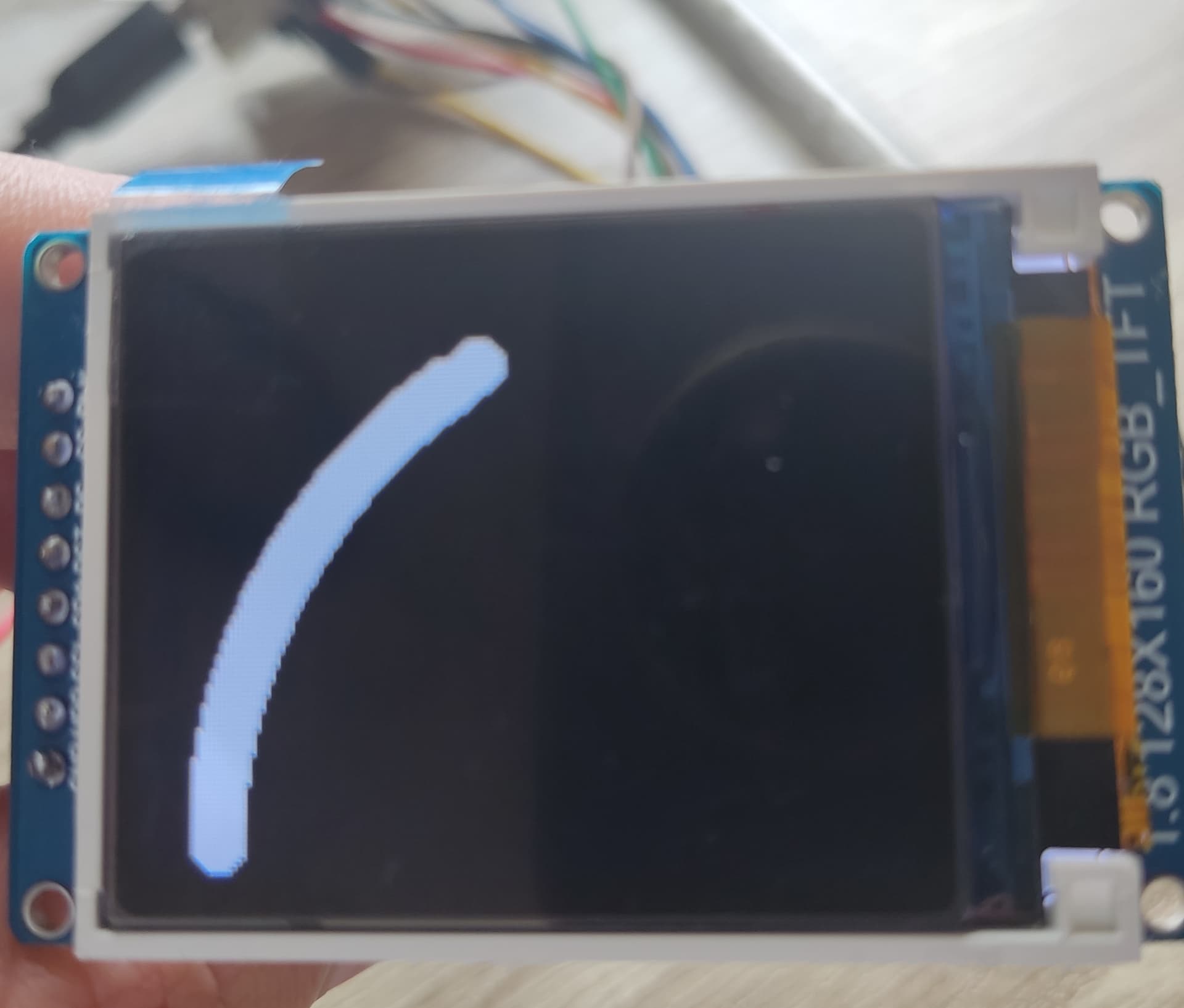
What I get with my code is
/*
 * This ESP32 code is created by esp32io.com
 *
 * This ESP32 code is released in the public domain
 *
 * For more detail (instruction and wiring diagram), visit https://esp32io.com/tutorials/esp32-touch-sensor
 */
#include <SPI.h>
#include <Adafruit_GFX.h>    // Core graphics library
#include <Adafruit_ST7735.h> // Hardware-specific library

#define TFT_CS        5
#define TFT_RST        4 // Or set to -1 and connect to Arduino RESET pin
#define TFT_DC         2
#define SENSOR_PIN  13 // ESP32 pin GIOP18 connected to the sensor's SIGNAL pin

#include "bitmaps.h"
#include "bitmapsLarge.h"
const int potPin= 13; // Analog Pin
int potValue;         // Potentiometer
float voltage= 0;
int pstate=0;

Adafruit_ST7735 tft = Adafruit_ST7735(TFT_CS, TFT_DC, TFT_RST);
void setup() {
  // initialize serial communication at 9600 bits per second:
  Serial.begin(115200);
  // initialize the ESP32's pin as aninput
  pinMode(SENSOR_PIN, INPUT);
  tft.initR(INITR_BLACKTAB);
   tft.fillScreen(ST7735_BLACK);


  // Use this initializer if using a 1.8" TFT screen:
 // tft.initR(INITR_BLACKTAB);      // Init ST7735S chip, black tab
  tft.setRotation(1); // set display orientation

}

void loop() {

    int x;           // x value
    int y;           // y value
    int x0=130;      // x0 value for cordinate beggining relocation
    int y0=120;      // y0 value for cordinate beggining relocation
    int r=120;       // radius of from x0,y0 to circle (x,y)
    int u;           //Angle


potValue= analogRead(potPin);  /// input signal for potentiometer
voltage=(3.3/4095.0)*potValue;   // potentiometer input to 3.3V calc 0-3.3V
  u=round(voltage*0.476);          // Angle 1.57 rad=90 deg, 1.57/3.3V=0.476
    x=r*cos(u);                     // Calculation of x of circle
    y=r*sin(u);                  // Calculation of y of circle


 tft.fillCircle(x0-x,y0-y,5,ST7735_WHITE); //Draws circle 5-cicrcle radius


delay(1);    //Potentiomenter input signal delay reading

}
i am not sure if it work.
my plan is draw sector from 0 to needed angle in white, and erase with black if value go smaller.
/*
   This ESP32 code is created by esp32io.com
   This ESP32 code is released in the public domain
   For more detail (instruction and wiring diagram), visit https://esp32io.com/tutorials/esp32-touch-sensor
*/
#include <SPI.h>
#include <Adafruit_GFX.h>    // Core graphics library
#include <Adafruit_ST7735.h> // Hardware-specific library

#define TFT_CS        5
#define TFT_RST       4 // Or set to -1 and connect to Arduino RESET pin
#define TFT_DC        2

#include "bitmaps.h"
#include "bitmapsLarge.h"
const int potPin = 13; // Analog Pin
int potValue;         // Potentiometer
float Radian = 0;
int pstate = 0;

Adafruit_ST7735 tft = Adafruit_ST7735(TFT_CS, TFT_DC, TFT_RST);
void setup() {
  // initialize serial communication at 9600 bits per second:
  Serial.begin(115200);
  // initialize the ESP32's pin as aninput
  pinMode(potPin, INPUT);
  tft.initR(INITR_BLACKTAB);
  tft.fillScreen(ST7735_BLACK);

  // Use this initializer if using a 1.8" TFT screen:
  // tft.initR(INITR_BLACKTAB);      // Init ST7735S chip, black tab
  tft.setRotation(1); // set display orientation
}

void loop() {

  static int x = 0;         // x value
  static int y = 0;         // y value
  const int x0 = 130;    // x0 value for cordinate beggining relocation
  const int y0 = 120;    // y0 value for cordinate beggining relocation
  const int r = 120;     // radius of from x0,y0 to circle (x,y)
  static int OldPotValue = 0;

  potValue = analogRead(potPin); /// input signal for potentiometer

  Radian = (float)potValue / 2608.9172;    // Angle 1.57 rad = 90 deg = 4096 analog units
  x = r * cos(Radian);              // Calculation of x of circle
  y = r * sin(Radian);              // Calculation of y of circle

  if (OldPotValue < potValue)tft.fillCircle(x0 - x, y0 - y, r, ST7735_WHITE); //Draws circle 5-cicrcle radius
  else tft.fillCircle(x0 - x, y0 - y, r, ST7735_BLACK);
  OldPotValue = potValue;
  delay(1);    //Potentiomenter input signal delay reading
}
I had to set the r in tft.fillCricle to 5.
r-defined is the length of of arc.
/*
   This ESP32 code is created by esp32io.com
   This ESP32 code is released in the public domain
   For more detail (instruction and wiring diagram), visit https://esp32io.com/tutorials/esp32-touch-sensor
*/
#include <SPI.h>
#include <Adafruit_GFX.h>    // Core graphics library
#include <Adafruit_ST7735.h> // Hardware-specific library

#define TFT_CS        5
#define TFT_RST       4 // Or set to -1 and connect to Arduino RESET pin
#define TFT_DC        2

#include "bitmaps.h"
#include "bitmapsLarge.h"
const int potPin = 13; // Analog Pin
int potValue;         // Potentiometer
float Radian = 0;
int pstate = 0;

Adafruit_ST7735 tft = Adafruit_ST7735(TFT_CS, TFT_DC, TFT_RST);
void setup() {
  // initialize serial communication at 9600 bits per second:
  Serial.begin(115200);
  // initialize the ESP32's pin as aninput
  pinMode(potPin, INPUT);
  tft.initR(INITR_BLACKTAB);
  tft.fillScreen(ST7735_BLACK);

  // Use this initializer if using a 1.8" TFT screen:
  // tft.initR(INITR_BLACKTAB);      // Init ST7735S chip, black tab
  tft.setRotation(1); // set display orientation
}

void loop() {

  static int x = 0;         // x value
  static int y = 0;         // y value
  const int x0 = 130;    // x0 value for cordinate beggining relocation
  const int y0 = 120;    // y0 value for cordinate beggining relocation
  const int r = 120;     // radius of from x0,y0 to circle (x,y)
  static int OldPotValue = 0;

  potValue = analogRead(potPin); /// input signal for potentiometer

  Radian = (float)potValue / 2608.9172;    // Angle 1.57 rad = 90 deg = 4096 analog units
  x = r * cos(Radian);              // Calculation of x of circle
  y = r * sin(Radian);              // Calculation of y of circle

  if (OldPotValue < potValue)tft.fillCircle(x0 - x, y0 - y, 5, ST7735_WHITE); //Draws circle 5-cicrcle radius
  else tft.fillCircle(x0 - x, y0 - y, 5, ST7735_BLACK);

  delay(1);    //Potentiomenter input signal delay reading
}
With that code, circles form a progress bar line (0 -90 deg)
When you reduce the input on potentiometer, it doesn't delete the line going from 90 towards 0.
It creates a black circle in 0 degrees ( x,y)
Save the previous temp in a different variable before you read the new one and compare current with previous values to determine whether it has changed
Basically I have to do this to compare the values if (OldPotValue < potValue)tft.fillCircle(x0 - x, y0 - y, 5, ST7735_WHITE); //Draws circle 5-cicrcle radius else tft.fillCircle(x0 - x, y0 - y, 5, ST7735_BLACK);
I think to solve the black dot just reverse calculate the 90 deg for x,y and then that value-Prev value-x0, same for y0 i will try it now
@cedarlakeinstruments
My condolence if it true. I think I say the project, But it's too overwhelming for my level, i just started playing with these microcontroller.
I found this code from user robot
if (val > valOld){//if the bar is longer...add
        //270/sensorMax[0] gives scaling for a 270 degree gauge
        for(angle = ((float)valOld*270/sensorMax[0]); angle <= (((float)val*270/sensorMax[0])); angle+=1){ //the "+=1" can be changed for more "fill in" of the arc (gets noticeable at 5)
        rad = angle * PI / 180;
        tft.fillCircle( (80-((int)(sin(rad)*43.0) ) ), (70+( (int)(cos(rad)*43.0))), 5,barColor);
      }
    }
    if (val < valOld){//if the bar is shorter...erase
      for(angle = (((float)valOld*270/sensorMax[0])); angle >= ((float)val*270/sensorMax[0]); angle-=1){ //the "+=1" can be changed for more "fill in" of the arc (gets noticeable at 5)
      rad = angle * PI / 180;
      tft.fillCircle( (80-((int)(sin(rad)*43.0) ) ), (70+( (int)(cos(rad)*43.0))), 5,background);
    }```

But i don't understand it, I'd like to figure how it works
@kolaha
Your code works. (When I turn the potentiometer clockwise 0>3,3v) it draws a white line (0>90 deg) That part works perfect
Example. If the maximum value is 80, and i turn my potentiometer counter clockwise, to 50 degrees, erase the previus max value(80) and display the line @50 degrees
It should delete from top towards the bottom left corner
Like progress bar that goes not only 0-100 but also from 100-0 ( this way deleting the previous Max value, if it's replaced by newMax value
  if (OldPotValue < potValue)tft.fillCircle(x0 - x, y0 - y, 5, ST7735_WHITE); //Draws circle 5-cicrcle radius
  else tft.fillCircle(x-x0, y-y0, 5, ST7735_BLACK);

  delay(1);    //Potentiomenter input signal delay reading
}
If I put it like this
It can draw white line from 90 towards 0,
and also from 0 towards 90
How can I now set this
90 towards 0 to be in black to delete the white line that i draw going from 0-90
EDIT:
For some reason
When I turn the potentiometer clockwise it draws a line. - OK
When I turn it clockwise - i have to turn it towards the beginning to it to delete the at @0 degrees. Maybe the function is not ok?
/*
   This ESP32 code is created by esp32io.com
   This ESP32 code is released in the public domain
   For more detail (instruction and wiring diagram), visit https://esp32io.com/tutorials/esp32-touch-sensor
*/
#include <SPI.h>
#include <Adafruit_GFX.h>    // Core graphics library
#include <Adafruit_ST7735.h> // Hardware-specific library

#define TFT_CS        5
#define TFT_RST       4 // Or set to -1 and connect to Arduino RESET pin
#define TFT_DC        2

#include "bitmaps.h"
#include "bitmapsLarge.h"
const int potPin = 13; // Analog Pin
int potValue;         // Potentiometer
float Radian = 0;

const int x0 = 130;    // x0 value for cordinate beggining relocation
const int y0 = 120;    // y0 value for cordinate beggining relocation
const int r = 120;     // radius of from x0,y0 to circle (x,y)

Adafruit_ST7735 tft = Adafruit_ST7735(TFT_CS, TFT_DC, TFT_RST);
void setup() {
  // initialize serial communication at 9600 bits per second:
  Serial.begin(115200);
  // initialize the ESP32's pin as aninput
  pinMode(potPin, INPUT);
  tft.initR(INITR_BLACKTAB);
  tft.fillScreen(ST7735_BLACK);

  // Use this initializer if using a 1.8" TFT screen:
  // tft.initR(INITR_BLACKTAB);      // Init ST7735S chip, black tab
  tft.setRotation(1); // set display orientation
}

void loop() {

  static int x = 0;         // x value
  static int y = 0;         // y value
  static int OldPotValue = 0;

  potValue = analogRead(potPin); /// input signal for potentiometer

  Radian = (float)potValue / 2608.9172;    // Angle 1.57 rad = 90 deg = 4096 analog units
  x = r * cos(Radian);              // Calculation of x of circle
  y = r * sin(Radian);              // Calculation of y of circle

  if (OldPotValue < potValue)tft.fillCircle(x0 - x, y0 - y, 5, ST7735_WHITE); //Draws circle 5-cicrcle radius
  else {
    tft.fillCircle(x0 - r * cos(Radian + 0.017), y0 - r * sin(Radian + 0.017), 8, ST7735_BLACK);
    tft.fillCircle(x0 - x, y0 - y, 5, ST7735_WHITE);
  }
  OldPotValue = potValue;

}
@kolaha
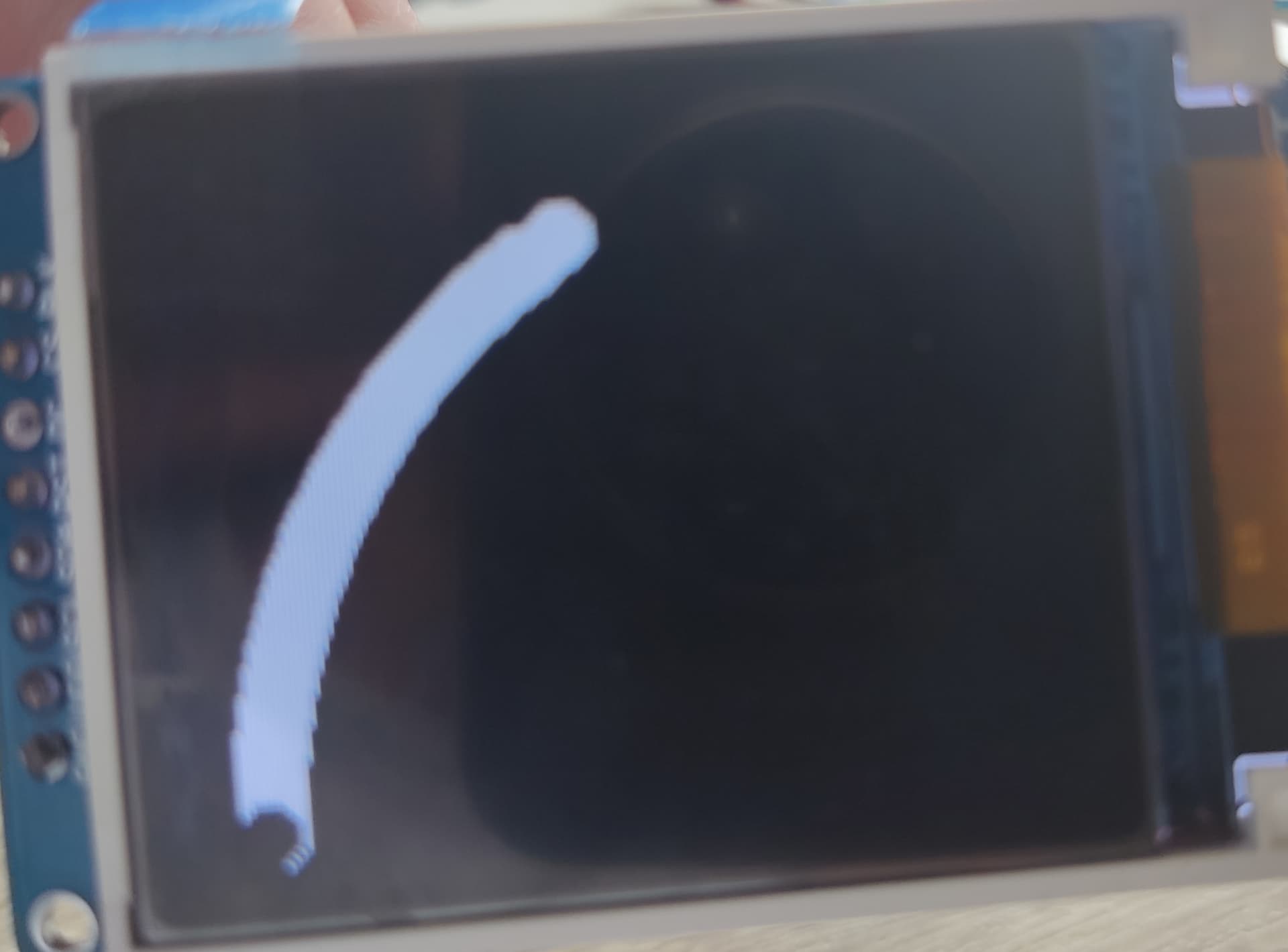
Thank you, this one woorks its not smooth ( maybe the potentiometer is sensitive, but its the way it is. I tried setting delay 10, 15 and its a bit better but it still leaves some marks behind.
Here is how it looks with no delay
EDIT: I think to reduce the flickering I need a noise filter on my potentiometer, I've tried running average it helps a bit.