Code for motor nema17

Hi, could someone please change this code for me to use the indicated button to change direction. Now it works, but as soon as the engine gets a smaller load, it changes direction by itself. Thank you for your help
`#include <Stepper.h>

const int stepsPerRevolution = 300;
Stepper myStepper(stepsPerRevolution, 8, 9, 10, 11);

const byte PinBut = 2;
byte butLst;

enum { Idle, CW, CCW };
int state = Idle;

// -----------------------------------------------------------------------------
void loop ()
{
// process state
switch (state) {
case Idle:
break;

case CCW:
    myStepper.step (-1);
    break;

case CW:
    myStepper.step (1);
    break;
}

// check for button press
byte but = digitalRead (PinBut);
if (butLst != but)  {
    butLst = but;
    delay (20);                 // debounce
    if (LOW == but) {
        if (CCW < ++state)     // advance state
            state = Idle;
        Serial.println (state);
    }
}

}

// -----------------------------------------------------------------------------
void setup () {
Serial.begin (9600);

myStepper.setSpeed (200);

pinMode (PinBut, INPUT_PULLUP);
butLst = digitalRead (PinBut);

}`

Hello @lukyzeu

Here is where you will change direction...

    case CCW:
      myStepper.step (-1);
      break;

    case CW:
      myStepper.step (1);
      break;

Rather than using "-1" and "1", you should use "-stepsPerRevolution" and "stepsPerRevolution"

    case CCW:
      myStepper.step (-stepsPerRevolution);
      break;

    case CW:
      myStepper.step (stepsPerRevolution);
      break;

You should follow this link: How to use this forum - please read

It is very unlikely that this is a software-problem
Why should the software change anthing just because a mechanical load is applied to your steppermotor????
it is very likely that this is a hardware-problem

And is there any way to solve it?

May I ask what driver you are using for the stepper motor?

What is the motor power supply?

Please post a wiring diagram.


Photos are of marginal utility. Please post a schematic or wiring diagram. Hand drawn, photographed and posted is fine. Include all pin names/numbers, components, their part numbers and/or values and power supplies.

Please post specs of the power supply.

The ancient and inefficient L298 driver is not appropriate for a modern bipolar stepper motor. Those motors require a current controlled driver.

Would you like help for choosing an appropriate stepper driver? if so, please post a data sheet for the stepper motor.

I still have the A4988 motor driver at home, which I can use, but I would need help on how to connect everything

The Pololu A4988 page will help with that. You will need a power supply with a minimum 8V output.

Make sure that you properly set the coil current limit before using the stepper. The coil current should be found in the motor data sheet. Set the current to less than or equal to the spec current. To set the current limit you will need to know the value of the sense resistor on the A4988 driver board. Then enter the value of the resistor and the required coil current into the formula Vref = Imot x 8 x Rsen where Imot = the coil current and Rsen = the value of the sense resistor. The Pololu A4988 page covers how to set the Vref but you must use the sense resistor value on YOUR board. This page shows how to locate the sense resistor.

and could you send me some wiring diagram?

What about this do you not understand?

image

Here is a simple bounce example for a step/dir type driver. Make the step and direction pins the pins of your choice.

// simple step/dir stepper bounce test by groundfungus
// aka charlie goulding

const byte stepPin = 2; //  set to pin of your choice
const byte directionPin = 5;  // set to pin of your choice

int stepsToTake = 100;
unsigned long stepDelay = 20;  // milliseconds to set stepper speed

void setup()
{
   Serial.begin(115200);
   Serial.println("Starting Stepper bounce demo ");

   pinMode(directionPin, OUTPUT);
   pinMode(stepPin, OUTPUT);
}

void loop()
{
   digitalWrite(directionPin, HIGH);
   for (int n = 0; n < stepsToTake; n++)
   {
      singleStep();  // 10 milliseconds per step
      delay(stepDelay);
   }

   digitalWrite(directionPin, LOW);
   for (int n = 0; n < stepsToTake; n++)
   {
      singleStep();  // 10 milliseconds per step
      delay(stepDelay);
   }
}

void singleStep()
{
   digitalWrite(stepPin, HIGH);
   delayMicroseconds(10);
   digitalWrite(stepPin, LOW);
}

I have this one https://dratek.cz/arduino/1133-motor-driver-a4988-pro-reprap-3d-tiskarny.html

and would it be connected to a non-soldering field, or how to connect it all, and would it be possible to somehow connect the button there so that the direction changes when it is clicked? I have a 12V power source, is that okay?

All the A4988 drivers connect the same. The diagram on the Pololu page will apply to your driver.

You can connect with a quality solderless breadboard for temporary testing, though that is not the best, at all. Better would be to solder the parts to a protoboard or use a CNC shield to mount the drivers and connect the steppers. I like the CNC shields for convenience.

Sure, like this. Tested on real hardware. The button wiring and the state change detection is shown in my tutorial. >> State change detection for active LOW inputs

// simple step/dir stepper toggle direction with button test by groundfungus
// aka charlie goulding

const byte stepPin = 2; //  set to pin of your choice
const byte directionPin = 5;  // set to pin of your choice
const byte buttonPin = 9;

int stepsToTake = 100;
unsigned long stepDelay = 20;  // milliseconds to set stepper speed

void setup()
{
   Serial.begin(115200);
   Serial.println("Starting Stepper button toggle direction");

   pinMode(directionPin, OUTPUT);
   pinMode(stepPin, OUTPUT);
   pinMode(buttonPin, INPUT_PULLUP);
}

void loop()
{
   static bool lastButtonState = HIGH;
   static unsigned long timer = 0;
   unsigned long interval = 20;
   if (millis() - timer >= interval)
   {
     
      timer = millis();
      bool buttonState = digitalRead(buttonPin);
      if (buttonState != lastButtonState)
      {
         
          Serial.println("time");
         if (buttonState == LOW)
         {
            digitalWrite(directionPin, !digitalRead(directionPin)); // toggle direction             
         }
         lastButtonState = buttonState;
      }
   }
   singleStep();  // 10 milliseconds per step
   delay(stepDelay);
}

void singleStep()
{
   digitalWrite(stepPin, HIGH);
   delayMicroseconds(10);
   digitalWrite(stepPin, LOW);
}

This is not a matter of how to connect the button.
The button could be connected as INPUT_PULLUP or as pull-down

This is a pure software-thing.
You add variable that stores the actual direction
and then do
as pseudo-code

if (actualDirection == forward) {
  actualDirection = backward;
}
else {
  actualDirection = forward;
}

best regards Stefan

So I connected it according to these instructions How to drive a stepper motor easily using A4988 and Arduino - YouTube
and it works, only the motor as soon as it gets a bit of a load can't turn any further and oscillates in the same place, by that I mean if it could be solved somehow? Thank you

You need to look up the datasheet of your stepper-motor.
Nema 17 is just a mechanical size what distance do the mounting screws have.
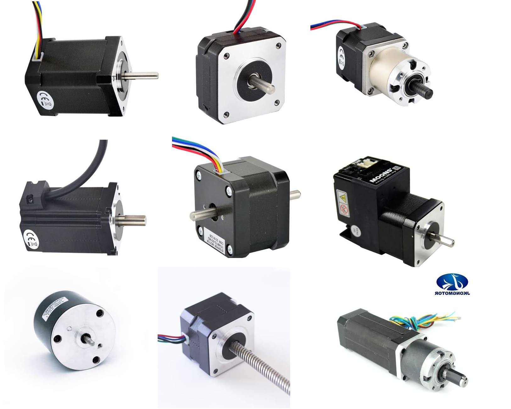
In the picture you can see all Nema17-stepper motors

In this datasheet you will find the rated current of the stepper-motor.
You have to adjust the current with this tiny potentiometer on the rated current
image

like described in the datasheet of your stepper-motor-driver

Additional you can not rotate a stepper-motor from zero rpm to 1500 rpm instantly
you have to accelerate / deccelerate the rpms

best regards Stefan

My motor is rated at 1.5 amps so what should I set it to? And is there a way to set the motor to be strong, but turn slower and not vibrate as much?

You can read this in the usermanual of your stepper-motor-driver.

If you use a more advanced stepper-motor-driver like a TMC2209 the motor can rotate very smooth and almost silent.

If you use microstepping your stepper-driver will create less noise for the cost that you have to increase the step-pulse-frequency . For really fast rotating an arduino-uno has a too slow clock.

best regards Stefan