Code from Arduino Mega to NodeMCU ESP8266

I have a project that has a:

  • Arduino Mega 2560

  • 4x water flow sensor
    image

  • 3x Gravity: analog water pressure sensor
    image

  • 4 solenoid valve
    image

and it looks like this:

regarding on why I used multiple water flow and water pressure sensor is because when there is a leak in the main line I can't pinpoint the where the leak is so in order to narrow the scope I added "sections"; Each section begins with a water flow and water pressure. The water pressure and water flow sensors in the beginning (before the solenoid valve) serves as a basis if the water is running or not; Because when there is a leak the water will divert to the bypass temporarily in order to fix the leak in the main line.

and the circuit:

The project works fine now with the use of arduino mega however I need to send the data reading of the water flow sensor , water pressure sensor, and control the solenoid valve through an app over wifi. I tried to use the wifi module esp8266 connected to the arduino mega but I can't make it work and tried to ask forums on how to but they suggested to use the NodeMCU ESP8266 to drive the whole project.

The problem is I don't know how to modify the code in order to make it work for NodeMCU ESP8266 and link it with BLYNK or Arduino IOT Cloud. I can make it work through some research and countless trial and errors but I am currently pressed for time. So please kind Sirs and Maams Help me :pray: :pray: :pray:

here is the code I used in arduino mega:


const byte sensors = 4;
const byte sensorPins[sensors] = {2, 3, 18, 19};
volatile unsigned long flow_frequency[sensors] = {0, 0, 0, 0}; // Measures flow sensor pulsesunsigned


void setup()
{
  Serial.begin(9600);        // open serial port, set the baud rate to 9600 bps
  for (byte s = 0; s < sensors; s++) {
    pinMode(sensorPins[s], INPUT_PULLUP);
  }
  attachInterrupt (digitalPinToInterrupt(sensorPins[0]), flow1, RISING);
  attachInterrupt (digitalPinToInterrupt(sensorPins[1]), flow2, RISING);
  attachInterrupt (digitalPinToInterrupt(sensorPins[2]), flow3, RISING);
  attachInterrupt (digitalPinToInterrupt(sensorPins[3]), flow4, RISING);

  
}
void loop()
{
static unsigned long cloopTime = millis();
if (millis() - cloopTime >= 100UL){
  cloopTime += 1000UL;
  water_Flow(0); 
  Serial.print(",");
  water_Flow(1);
  Serial.print(",");
  water_Flow(2);
  Serial.print(",");
  water_Flow(3);
  Serial.print(",");
}
  PressureSensor(A0, 0.47);
  Serial.print(",");
  PressureSensor(A0, 0.47);
  Serial.print(",");
  PressureSensor(A0, 0.07);
  Serial.println("");


}


void valve_On( int m_pin){
  pinMode(m_pin, OUTPUT); //set m_pin to output to control the valve
  digitalWrite(m_pin, HIGH); // set the output to HIGH to turn ON the valve
  
}

void valve_Off( int m_pin){
  pinMode(m_pin, OUTPUT);
  digitalWrite(m_pin, LOW); // set the output to LOW to turn OFF the valve
  
}

float  OffSet; // declared as float since it will contain decimals
float V, P;
void PressureSensor (int analogpin, float off){
  OffSet = off;
    V =  analogRead(analogpin) * 5.00 / 1024;     //Sensor output voltage
  P = (V - OffSet) ;             //Calculate water pressure
  

//if (P < 0){
//  P = 0.00;
//}
//  Serial.print("WaterPressure: ");
//  Serial.println(analogpin + 1);
//  Serial.print("Voltage:");
//  Serial.print(V, 3);
//  Serial.println("V");
//  Serial.print(" Pressure:");
  Serial.print(P);
//  Serial.println(" KPa");
//  Serial.println();

  delay(150);
  
}

void flow1() { // interrupt function 
  flow_frequency[0]++; // this will increment the  array flow_frequency[s]
}
void flow2() {
  flow_frequency[1]++;
}
void flow3(){
  flow_frequency[2]++;
}
void flow4(){
  flow_frequency[3]++;
}


float water_Flow (byte s) {
  static unsigned long l_hour = 0;
  static unsigned long flow_freq = 0; 
  
  noInterrupts();
  flow_freq = flow_frequency[s]; 
  flow_frequency[s] = 0; // this is used so that the reading of the water flow returns to 0 whenver it stops spinning and not stacking the reading
  interrupts();
    // Pulse frequency (Hz) = 7.5Q, Q is flow rate in L/min.
  l_hour = (flow_freq * 60 / 7.5); // (Pulse frequency x 60 min) / 7.5Q = flowrate in L/hour

//  Serial.print( "WaterFlow: ");
//  Serial.println(s);
  Serial.print(l_hour); // Print litres/hour
//  Serial.println(" L/hour");
  delay(150);
  if (s != 0){
    
    if(l_hour < 550){
      delay(5000);
      valve_On(7);
      valve_On(6);
      valve_On(8);
      valve_On(9);

      Serial.print("Leakage in section:" + (s+1)); 
     }
     else{
      valve_Off(7);
      valve_Off(6);
      valve_Off(8);
      valve_Off(9);
     }
     
  }
     
  }

I will follow this circuit to connect everything to the nodeMcu since I don't know how :laughing:

Well the first issue to address is that the nodeMCU only has 1 analog pin with a 0 - 1v input.
But the fritzing diagram behind your link is completely unreadable, i am not even going to try to make sense of that.
How about you convert that to a decent schematic.

ok sure thanks

All those flow sensors and valves reduce the water flow, is that okay ? is there only a small flow ?
Can you fix the cause of the problem and replace the bad pipes ?

It is impossible to check the circuit at circuito.io. It would take hours to follow every wire. I can not even zoom in enough. I tried to investigate it for 1 minute and that almost melted my brain :exploding_head:
A schematic that shows how it is wired would be helpful. Can you draw a schematic ?

The ESP8266 has only one analog input. You should at least start with the ESP32.
It is possible to do your project with a ESP32, but you have to check everything that it will work with 3.3V instead of 5V.
Adding a ESP32 for Wifi is not a bad idea. Both the Mega and the ESP32 have a spare hardware serial port for communication. You need a level shifter, because the ESP32 has no 5V tolerant pins.

I suggest to learn the ESP32, and decide along the way if you want to do your whole project with it, or attach it to the Mega board.
You can start here and read which pins can be used: https://randomnerdtutorials.com/esp32-pinout-reference-gpios/

The ESP32 has a number of weird things. For example, if you use Wifi then half of the analog inputs can not be used.

[ADDED] While I wrote this, Deva_Rishi already wrote the same.

sorry for the schematic it is indeed very hard to understand :rofl: I just used this website since I only drag and drop the components I need to use and it adds everything it needs to make it work

I tried to remove some sensors in order to make it less complicated. please tell me if it is still unreadable and I'll try to separate each sensor every schematic

It added this
image
I dont know what it is but the 3 analog water pressure sensor is connected here to connect to one analog pin

@Koepel regarding the reduce of water flow it is fine since it just a prototype I just need to make this work for demonstration purposes in our school and I wanted to add an app if possible to control it. But if I can't make it work until sunday I would just stick to the mega and discard the app

If you do it right you can manage just fine with a single analog input.

there is a big difference between controlling your device over WiFi world-wide or just locally in the local WiFi.

controlling it world-wide requires to use any kind of service that transfers the data "to the world"
This service would be some kind of dynDNS or anything like Blynk, remoteIO, RemoteME etc. etc. which all need configuration and an account through climbing up a learning curve.

If you stay within the local WiFi or if the ESP8266 acts as the access-point itself things can be easier depending on what approach you use.
Again withing local WiFi to use a webinterface can be done with different approaches each one with a learning-curve. Depending on what example-code you use the learning-curve can be 1 or 2 days or 1 to 4 weeks.

So just randomly choosing any example-code has a high chance to pick one of the very bad documented examples with the 4 weeks learning-curve.

trying to make it work over an app is likely to add another learning-curve for the app.

Attention!

Of course if somebody knows of an app that is "Click & play" of course post the link.
I want to explain a little bit what I mean with "Click & play"

Have to read a maximum of 2 pages of explanation and doing a maximum of 5 mouse-clicks per item
and the thing is really up and running.
Do you understand up and running

Whatever I came across until know requires:
10 to 20 pages of reading, additionally asking 5 to 10 questions in a user-forum
needing 20 to 50 mouse-clicks per item
writing code with configuring authentification tokens
etc. etc. etc.
This is the two weeks learning curve

As you have everything running on the Arduino Mega
a step inbetween can be to add send / and receive serial commands to the serial monitor as a step inbetween remotely controlling it with an ESP8266 nodeMCU.
Adding serial-prints to your Arduino-Mega-code that show the data

Making your Arduino-Mega-code receive commands from the serial-monitor that are processed to switch the valves

If this is working the new partner of the Arduino-Mega is the ESP8266 nodeMCU replacing the serial monitor

This would require to write code for the ESP8266 nodeMCU that does the send/receive over a serial connection and the WiFi-stuff.

A question would you be able to securly have an ESP32 on your table todays evening?
The ESP32 offers more opportunities that the ESP8266.
Anyway the ESP8266 is capable of doing the job too.

For this solution I have the ESP-Dash-library in mind.
The ESP-Dash-library offers Webinterface-functionality with pure C++-coding.
No need to learn a single line of HTML-code. All HTML-stuff is done in the background

Again: if somebody knows of a

very easy to adapt demo-code

that offers a webinterface accessible from the local WLAN
post a link
very easy to understand means

  • well documented
  • instensively commented example-code which makes it easy to modify without falling into traps

best regards Stefan

So here are some links how to install required libraries from GitHub
and the links on Github themselfs

For using the ESP-Dash-library some other libraries are required to install:
as there is

and ESP-Dash itself

My Demo-Code makes use of another library named SafeString which can be installed from the library-manager inside the Arduino-IDE.

Some other users here have the opinion
"it is important to learn the underlaying mechanisms of how to deal with original c_strings"
Yes honorable goal. From a practical point of view IMHO it is better to give newcomers SafeString than hoping for "the newcomer will learn enough to be able to use c_strings in a secure way" @these "C++purists": alternatively write down a easy to understand and entertaining tutorial to make it really happen that newcomers will really learn it! No time? Ok save some more time and do not whine about using SafeString

here is a alpha-state testcode that is testing send/receive with software-serial

// MACRO-START * MACRO-START * MACRO-START * MACRO-START * MACRO-START * MACRO-START *

// a detailed explanation how these macros work is given in this tutorial
// https://forum.arduino.cc/t/comfortable-serial-debug-output-short-to-write-fixed-text-name-and-content-of-any-variable-code-example/888298

#define dbg(myFixedText, variableName) \
  Serial.print( F(#myFixedText " "  #variableName"=") ); \
  Serial.println(variableName);
// usage: dbg("1:my fixed text",myVariable);
// myVariable can be any variable or expression that is defined in scope

#define dbgi(myFixedText, variableName,timeInterval) \
  do { \
    static unsigned long intervalStartTime; \
    if ( millis() - intervalStartTime >= timeInterval ){ \
      intervalStartTime = millis(); \
      Serial.print( F(#myFixedText " "  #variableName"=") ); \
      Serial.println(variableName); \
    } \
  } while (false);
// usage: dbgi("2:my fixed text",myVariable,1000);
// myVariable can be any variable or expression that is defined in scope
// third parameter is the time in milliseconds that must pass by until the next time a
// Serial.print is executed
// end of macros dbg and dbgi
// MACRO-END * MACRO-END * MACRO-END * MACRO-END * MACRO-END * MACRO-END * MACRO-END *

#define CodeVersion "Code-Version 006"

//#include <Arduino.h>
#if defined(ESP8266)
/* ESP8266 Dependencies */
#include <ESP8266WiFi.h>
#include <ESPAsyncTCP.h>
#include <ESPAsyncWebServer.h>
#elif defined(ESP32)
/* ESP32 Dependencies */
#include <WiFi.h>
#include <AsyncTCP.h>
#include <ESPAsyncWebServer.h>
#endif
#include <ESPDash.h>

#include <SoftwareSerial.h>
const byte SoftSerTx_Pin = 15;
const byte SoftSerRx_Pin = 13;
const boolean invertLogic = false;
const byte buffersize = 256;
SoftwareSerial SoftSerial(SoftSerRx_Pin, SoftSerTx_Pin, invertLogic);
const int SoftBaudRate = 115200;

#include <SafeString.h>
createSafeString(WaterFlow1_SS,  32);
createSafeString(WaterFlow2_SS,  32);
createSafeString(WaterFlow3_SS,  32);

createSafeString(WaterPressure1_SS,  32);
createSafeString(WaterPressure2_SS,  32);
createSafeString(WaterPressure3_SS,  32);
createSafeString(WaterPressure4_SS,  32);

#define MAX_CHARS 128
char receivedChars[MAX_CHARS];
createSafeString(SerialReceived_SS,  MAX_CHARS);

boolean newDataComplete = false;

/* Your SoftAP WiFi Credentials */
const char* ssid = "ESP-Dash-Demo"; // SSID
// ATTENTION password MUST have at least 8 characters
// otherwise you CAN'T connect !!!!
const char* password = "12345678"; // Password

boolean ByPassOpened = false;

int myDemoCounter;

/* Start Webserver */
AsyncWebServer myAsyncServer(80);

/* Attach ESP-DASH to AsyncWebServer */
ESPDash MyDashBoard(&myAsyncServer);

/* define Dashboard Cards
  Format - (Dashboard Instance, Card Type, Card Name, Card Symbol(optional) )
*/
//  Button Card Format - (Dashboard Instance, Card Type, descriptive Text)
Card MyByPassButton(&MyDashBoard, BUTTON_CARD, "open/close Bypass");

Card MyValve1Button(&MyDashBoard, BUTTON_CARD, "open/close valve 1");
Card MyValve2Button(&MyDashBoard, BUTTON_CARD, "open/close valve 2");
Card MyValve3Button(&MyDashBoard, BUTTON_CARD, "open/close valve 3");
Card MyValve4Button(&MyDashBoard, BUTTON_CARD, "open/close valve 4");

Card WaterFlowCard1(&MyDashBoard, GENERIC_CARD, "Waterflow 1", "L/s");
Card WaterFlowCard2(&MyDashBoard, GENERIC_CARD, "Waterflow 1", "L/s");
Card WaterFlowCard3(&MyDashBoard, GENERIC_CARD, "Waterflow 1", "L/s");

Card WaterPressureCard1(&MyDashBoard, GENERIC_CARD, "Waterpressure 1", "PSI");
Card WaterPressureCard2(&MyDashBoard, GENERIC_CARD, "Waterpressure 2", "PSI");
Card WaterPressureCard3(&MyDashBoard, GENERIC_CARD, "Waterpressure 3", "PSI");
Card WaterPressureCard4(&MyDashBoard, GENERIC_CARD, "Waterpressure 4", "PSI");


void PrintFileNameDateTime() {
  Serial.println( F("Code running comes from file ") );
  Serial.println( F(__FILE__) );
  Serial.print( F("  compiled ") );
  Serial.print( F(__DATE__) );
  Serial.print( F(" ") );
  Serial.println( F(__TIME__) );
  Serial.println( F(CodeVersion) );
}


void ESP_DashSetup() {

  // Attach Button Callback this function gets executed every time the Button is clicked
  MyByPassButton.attachCallback([&](bool MyByPassButtonState) {
    ByPassOpened = MyByPassButtonState;
    Serial.println("MyByPassButton Triggered: " + String((MyByPassButtonState) ? "true" : "false"));
    MyByPassButton.update(MyByPassButtonState); //Make sure we update our button's value and send update to dashboard */
    MyDashBoard.sendUpdates();
  });

  Serial.println( F("ESP_DashSetup() done") );
}


// easy to use helper-function for non-blocking timing
boolean TimePeriodIsOver (unsigned long &startOfPeriod, unsigned long TimePeriod) {
  unsigned long currentMillis  = millis();
  if ( currentMillis - startOfPeriod >= TimePeriod ) {
    // more time than TimePeriod has elapsed since last time if-condition was true
    startOfPeriod = currentMillis; // a new period starts right here so set new starttime
    return true;
  }
  else return false;            // actual TimePeriod is NOT yet over
}

unsigned long MyTestTimer = 0;                   // Timer-variables MUST be of type unsigned long
const byte    OnBoard_LED = 2;


void BlinkHeartBeatLED(int IO_Pin, int BlinkPeriod) {
  static unsigned long MyBlinkTimer;
  pinMode(IO_Pin, OUTPUT);

  if ( TimePeriodIsOver(MyBlinkTimer, BlinkPeriod) ) {
    digitalWrite(IO_Pin, !digitalRead(IO_Pin) );
  }
}


void Start_AP_AsyncWebServer() {
  /* Start Access Point */
  WiFi.mode(WIFI_AP);
  WiFi.softAPConfig(IPAddress(192, 168, 4, 1), IPAddress(192, 168, 4, 1), IPAddress(255, 255, 255, 0));
  WiFi.softAP(ssid, password);
  Serial.print( F("IP Address: ") );
  Serial.println(WiFi.softAPIP());

  /* Start AsyncWebServer */
  myAsyncServer.begin();
  Serial.println( F("myAsyncServer.begin() done") );
  Serial.print( F("WiFi with name ") );
  Serial.print(ssid);
  Serial.print( F(" created WiFi-Accesspoint") );
  Serial.print( F("Connect to this WiFi Password is ") );
  Serial.println(password);
  Serial.println( F("then type into your browser") );
  Serial.print( F("http://") );
  Serial.println(WiFi.softAPIP());
}

void UpDateData() {
  if (ByPassOpened) {
    myDemoCounter++;
    WaterFlow1_SS  = "actual flow:";
    WaterFlow1_SS += myDemoCounter;
    WaterFlowCard1.update(WaterFlow1_SS.c_str());
    /* Send Updates to our Dashboard (realtime) */
    MyDashBoard.sendUpdates();
  }

  if (newDataComplete) { // new data received
    newDataComplete = false; // clear flag
    // and proces data
    WaterFlow2_SS = SerialReceived_SS;

    WaterFlowCard2.update(WaterFlow2_SS.c_str());
    MyDashBoard.sendUpdates();
  }
}


void SoftRecvWithStartEndMarkers() {
  static boolean recvInProgress = false;
  static byte ndx = 0;
  char startMarker = '<';
  char endMarker = '>';
  char rc;

  while (SoftSerial.available() > 0 && newDataComplete == false) {
    // if there are characters in the Rx-buffer (= SoftSerial.available())
    // and no endmarker is yet received (=newDataComplete == false
    rc = SoftSerial.read(); // read character  from Rx-buffer

    if (recvInProgress == true) {
      if (rc != endMarker) { // if it is NOT the endmarker
        SerialReceived_SS += rc; // add character to variable
        ndx++;                       // increase index by 1
        if (ndx >= MAX_CHARS) {      // if too many characters
          ndx = MAX_CHARS - 1;       // drop them
        }
      }
      else {
        SerialReceived_SS += rc; // add character
        ndx++;

        //receivedChars[ndx] = '\0'; // terminate the string
        recvInProgress = false;
        ndx = 0;
        newDataComplete = true;
      }
    }

    else if (rc == startMarker) {
      // startMarker found start collecting characters
      SerialReceived_SS  = ""; // delete last characters
      SerialReceived_SS += rc; // add new character
      //receivedChars[ndx] = rc;
      ndx++;
      recvInProgress = true;
    }
  }
} // end of void SoftRecvWithStartEndMarkers()


void setup() {
  Serial.begin(115200);
  Serial.println( F("Setup-Start") );
  SoftSerial.begin(SoftBaudRate);
  Serial.println( F("SoftSerial.begin(") );
  Serial.print(SoftBaudRate);
  Serial.println( F("); done") );
  SoftSerial.println("SoftSerial-Start");
  PrintFileNameDateTime();
  ESP_DashSetup();
  Start_AP_AsyncWebServer();

  myDemoCounter = 0;
  newDataComplete = false;
}


void loop() {

  BlinkHeartBeatLED(OnBoard_LED, 250);
  SoftRecvWithStartEndMarkers();

  if (newDataComplete) {
    Serial.print( F("SoftSerial received chars #") );
    Serial.print(SerialReceived_SS);
    Serial.print( F("#") );
  }


  if ( TimePeriodIsOver(MyTestTimer, 1000) ) {
    UpDateData();

    SoftSerial.print( F("Hi I'm Softserial at ") );
    SoftSerial.print(SoftBaudRate);
    SoftSerial.println( F(" baud") );
  }

}

This code is not ready to use but shows the principles how ESP-DASH must be coded

sorry for the lae reply stefan and thank you so much for the explanation. To answer your question yes I have an ESP32 right now

So here is a code-version that makes use of ESP-DASH that can be used with an ESP8266 or an ESP32. The code has conditional compiler-directives to use ESP8266-files or ESP32 files according to the board-adjustment of the Arduino-IDE

It is pretty advanced but not in a state to be ready to demonstrate everything. This code-version is advanced enough to show the principles.
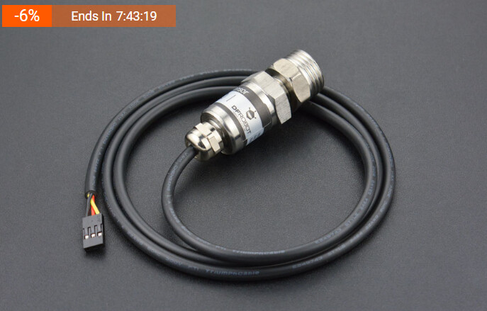
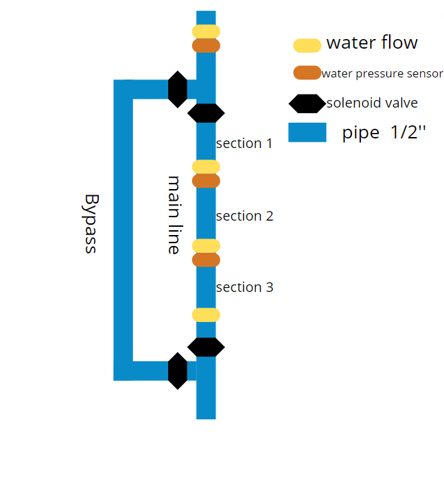
For testing purposes I added software-switches that simulate your flow-sensors and pressure-sensors

This is the code that must be flashed to the ESP32 who will act as the gateway to WiFi.
The data-exchange between Arduino Mega and ESP8266 (or ESP32 as well) is done through
a second serial interface. On Arduino Mega-side it uses Serial2
on ESP-side it uses software-serial

The advantage of this solution is you can use any Wifi-cabalbe device with any kind of browser to connect.
The second advantage is everything is done by simply coding C++. zero HTML-coding

You should use a voltage-level-converter between the 5V Arduino Mega and the 3.3V ESP32
For the serial connection
so here is the code

ESP32 / ESP8266

// MACRO-START * MACRO-START * MACRO-START * MACRO-START * MACRO-START * MACRO-START *
// Take it for granted at the moment scroll down to void setup
// start of macros dbg and dbgi
#define dbg(myFixedText, variableName) \
  Serial.print( F(#myFixedText " "  #variableName"=") ); \
  Serial.println(variableName);
// usage: dbg("1:my fixed text",myVariable);
// myVariable can be any variable or expression that is defined in scope

#define dbgi(myFixedText, variableName,timeInterval) \
  do { \
    static unsigned long intervalStartTime; \
    if ( millis() - intervalStartTime >= timeInterval ){ \
      intervalStartTime = millis(); \
      Serial.print( F(#myFixedText " "  #variableName"=") ); \
      Serial.println(variableName); \
    } \
  } while (false);
// usage: dbgi("2:my fixed text",myVariable,1000);
// myVariable can be any variable or expression that is defined in scope
// third parameter is the time in milliseconds that must pass by until the next time a
// Serial.print is executed
// end of macros dbg and dbgi
// MACRO-END * MACRO-END * MACRO-END * MACRO-END * MACRO-END * MACRO-END * MACRO-END *

#define CodeVersion "Code-Version 006"

//#include <Arduino.h>
#if defined(ESP8266)
/* ESP8266 Dependencies */
#include <ESP8266WiFi.h>
#include <ESPAsyncTCP.h>
#include <ESPAsyncWebServer.h>
#elif defined(ESP32)
/* ESP32 Dependencies */
#include <WiFi.h>
#include <AsyncTCP.h>
#include <ESPAsyncWebServer.h>
#endif
#include <ESPDash.h>

#include <SoftwareSerial.h>
const byte SoftSerTx_Pin = 15;
const byte SoftSerRx_Pin = 13;
const boolean invertLogic = false;
const byte buffersize = 256;
SoftwareSerial SoftSerial(SoftSerRx_Pin, SoftSerTx_Pin, invertLogic);
const int SoftBaudRate = 9600;

#include <SafeString.h>
createSafeString(WaterFlow1_SS,  32);
createSafeString(WaterFlow2_SS,  32);
createSafeString(WaterFlow3_SS,  32);
createSafeString(WaterFlow4_SS,  32);

createSafeString(WaterPressure1_SS,  32);
createSafeString(WaterPressure2_SS,  32);
createSafeString(WaterPressure3_SS,  32);


#define MAX_CHARS 256
char receivedChars[MAX_CHARS];
createSafeString(SerialReceived_SS,  MAX_CHARS);
createSafeString(MultiPurp_SS,  MAX_CHARS);

createSafeString(TokenSubStr, 16);
char delimiters[] = ","; // just comma for delimiter, could also use ",;" if comma or semi-colon seperated fields
createSafeString(Data_SS,  16);

size_t BeginOfSubStr;
size_t EndOfSubStr;

boolean newDataComplete = false;

/* Your SoftAP WiFi Credentials */
const char* ssid = "ESP-Dash-Demo"; // SSID
// ATTENTION password MUST have at least 8 characters
// otherwise you CAN'T connect !!!!
const char* password = "12345678"; // Password

boolean ByPassOpened = false;

int myDemoCounter;

/* Start Webserver */
AsyncWebServer myAsyncServer(80);

/* Attach ESP-DASH to AsyncWebServer */
ESPDash MyDashBoard(&myAsyncServer);

/* define Dashboard Cards
  Format - (Dashboard Instance, Card Type, Card Name, Card Symbol(optional) )
*/
//  Button Card Format - (Dashboard Instance, Card Type, descriptive Text)
Card MyByPassButton(&MyDashBoard, BUTTON_CARD, "open/close Bypass");

Card MyValve1Button(&MyDashBoard, BUTTON_CARD, "open/close valve 1");
Card MyValve2Button(&MyDashBoard, BUTTON_CARD, "open/close valve 2");
Card MyValve3Button(&MyDashBoard, BUTTON_CARD, "open/close valve 3");
Card MyValve4Button(&MyDashBoard, BUTTON_CARD, "open/close valve 4");

Card WaterFlowCard1(&MyDashBoard, GENERIC_CARD, "Waterflow 1", "L/h");
Card WaterFlowCard2(&MyDashBoard, GENERIC_CARD, "Waterflow 2", "L/h");
Card WaterFlowCard3(&MyDashBoard, GENERIC_CARD, "Waterflow 3", "L/h");
Card WaterFlowCard4(&MyDashBoard, GENERIC_CARD, "Waterflow 4", "L/h");

Card WaterPressureCard1(&MyDashBoard, GENERIC_CARD, "Waterpressure 1", "PSI");
Card WaterPressureCard2(&MyDashBoard, GENERIC_CARD, "Waterpressure 2", "PSI");
Card WaterPressureCard3(&MyDashBoard, GENERIC_CARD, "Waterpressure 3", "PSI");


void PrintFileNameDateTime() {
  Serial.println( F("Code running comes from file ") );
  Serial.println( F(__FILE__) );
  Serial.print( F("  compiled ") );
  Serial.print( F(__DATE__) );
  Serial.print( F(" ") );
  Serial.println( F(__TIME__) );
  Serial.println( F(CodeVersion) );
}


void ESP_DashSetup() {

  // Attach Button Callback this function gets executed every time the Button is clicked
  MyByPassButton.attachCallback([&](bool MyByPassButtonState) {
    ByPassOpened = MyByPassButtonState;
    Serial.println("MyByPassButton Triggered: " + String((MyByPassButtonState) ? "true" : "false"));
    MyByPassButton.update(MyByPassButtonState); //Make sure we update our button's value and send update to dashboard */
    MyDashBoard.sendUpdates();
  });

  Serial.println( F("ESP_DashSetup() done") );
}


// easy to use helper-function for non-blocking timing
boolean TimePeriodIsOver (unsigned long &startOfPeriod, unsigned long TimePeriod) {
  unsigned long currentMillis  = millis();
  if ( currentMillis - startOfPeriod >= TimePeriod ) {
    // more time than TimePeriod has elapsed since last time if-condition was true
    startOfPeriod = currentMillis; // a new period starts right here so set new starttime
    return true;
  }
  else return false;            // actual TimePeriod is NOT yet over
}

unsigned long MyTestTimer = 0;                   // Timer-variables MUST be of type unsigned long
const byte    OnBoard_LED = 2;


void BlinkHeartBeatLED(int IO_Pin, int BlinkPeriod) {
  static unsigned long MyBlinkTimer;
  pinMode(IO_Pin, OUTPUT);

  if ( TimePeriodIsOver(MyBlinkTimer, BlinkPeriod) ) {
    digitalWrite(IO_Pin, !digitalRead(IO_Pin) );
  }
}


void Start_AP_AsyncWebServer() {
  /* Start Access Point */
  WiFi.mode(WIFI_AP);
  WiFi.softAPConfig(IPAddress(192, 168, 4, 1), IPAddress(192, 168, 4, 1), IPAddress(255, 255, 255, 0));
  WiFi.softAP(ssid, password);
  Serial.print( F("IP Address: ") );
  Serial.println(WiFi.softAPIP());

  /* Start AsyncWebServer */
  myAsyncServer.begin();
  Serial.println( F("myAsyncServer.begin() done") );
  Serial.print( F("WiFi with name ") );
  Serial.print(ssid);
  Serial.print( F(" created WiFi-Accesspoint") );
  Serial.print( F("Connect to this WiFi Password is ") );
  Serial.println(password);
  Serial.println( F("then type into your browser") );
  Serial.print( F("http://") );
  Serial.println(WiFi.softAPIP());
}

void UpDateData() {
  if (ByPassOpened) {
    myDemoCounter++;
    WaterFlow1_SS  = "actual flow:";
    WaterFlow1_SS += myDemoCounter;
    WaterFlowCard1.update(WaterFlow1_SS.c_str());
    /* Send Updates to our Dashboard (realtime) */
    MyDashBoard.sendUpdates();
  }
}


void ExtractData() {
  if (newDataComplete) { // new data received
    newDataComplete = false; // clear flag
    // and proces data
    //WaterFlow2_SS = SerialReceived_SS;
    MultiPurp_SS = SerialReceived_SS;

    MultiPurp_SS.nextToken(TokenSubStr, delimiters, true);
    BeginOfSubStr = TokenSubStr.indexOf("W1=") + 3;
    EndOfSubStr   = TokenSubStr.indexOf(",")  - 1;
    Serial.print("TokenSubStr#");
    Serial.print(TokenSubStr);
    Serial.println("#");
    Serial.println();

    TokenSubStr.substring(Data_SS, BeginOfSubStr, EndOfSubStr);
    Serial.print("Data_SS#");
    Serial.print(Data_SS);
    Serial.println("#");
    Serial.println();

    MultiPurp_SS.nextToken(TokenSubStr, delimiters, true);
    BeginOfSubStr = TokenSubStr.indexOf("W2=") + 3;
    EndOfSubStr   = TokenSubStr.indexOf(",")  - 1;
    Serial.print("TokenSubStr#");
    Serial.print(TokenSubStr);
    Serial.println("#");
    Serial.println();

    TokenSubStr.substring(Data_SS, BeginOfSubStr, EndOfSubStr);
    Serial.print("Data_SS#");
    Serial.print(Data_SS);
    Serial.println("#");
    Serial.println();

    WaterFlowCard2.update(Data_SS.c_str());
    MyDashBoard.sendUpdates();
  }
}


void SoftRecvWithStartEndMarkers() {
  static boolean recvInProgress = false;
  static byte ndx = 0;
  char startMarker = '<';
  char endMarker = '>';
  char rc;

  while (SoftSerial.available() > 0 && newDataComplete == false) {
    // if there are characters in the Rx-buffer (= SoftSerial.available())
    // and no endmarker is yet received (=newDataComplete == false
    rc = SoftSerial.read(); // read character  from Rx-buffer

    if (recvInProgress == true) {
      if (rc != endMarker) { // if it is NOT the endmarker
        SerialReceived_SS += rc; // add character to variable
        ndx++;                       // increase index by 1
        if (ndx >= MAX_CHARS) {      // if too many characters
          ndx = MAX_CHARS - 1;       // drop them
        }
      }
      else {
        SerialReceived_SS += rc; // add character
        ndx++;

        //receivedChars[ndx] = '\0'; // terminate the string
        recvInProgress = false;
        ndx = 0;
        newDataComplete = true;
      }
    }

    else if (rc == startMarker) {
      // startMarker found start collecting characters
      SerialReceived_SS  = ""; // delete last characters
      SerialReceived_SS += rc; // add new character
      //receivedChars[ndx] = rc;
      ndx++;
      recvInProgress = true;
    }
  }
} // end of void SoftRecvWithStartEndMarkers()


void setup() {
  Serial.begin(115200);
  Serial.println( F("Setup-Start") );
  SoftSerial.begin(SoftBaudRate);
  Serial.println( F("SoftSerial.begin(") );
  Serial.print(SoftBaudRate);
  Serial.println( F("); done") );
  SoftSerial.println("SoftSerial-Start");
  PrintFileNameDateTime();
  ESP_DashSetup();
  Start_AP_AsyncWebServer();

  myDemoCounter = 0;
  newDataComplete = false;
}


void loop() {

  BlinkHeartBeatLED(OnBoard_LED, 250);
  SoftRecvWithStartEndMarkers();

  if ( TimePeriodIsOver(MyTestTimer, 1000) ) {
    if (newDataComplete) {
      //newDataComplete = false;
      Serial.print( F("SoftSerial received chars #") );
      Serial.print(SerialReceived_SS);
      Serial.println( F("#") );
      ExtractData(); 
    }
    UpDateData();

    SoftSerial.print( F("Hi I'm Softserial at ") );
    SoftSerial.print(SoftBaudRate);
    SoftSerial.println( F(" baud") );
  }

}

Your Arduino-Mega-Code modified to communicate over Serial2

#include <SafeString.h>
createSafeString(DataToSend_SS,  256);

createSafeString(WaterFlow1_SS,  16);
createSafeString(WaterFlow2_SS,  16);
createSafeString(WaterFlow3_SS,  16);
createSafeString(WaterFlow4_SS,  16);

createSafeString(WaterPressure1_SS,  16);
createSafeString(WaterPressure2_SS,  16);
createSafeString(WaterPressure3_SS,  16);

const byte sensors = 4;
const byte sensorPins[sensors] = {2, 3, 18, 19};
volatile unsigned long flow_frequency[sensors] = {0, 0, 0, 0}; // Measures flow sensor pulsesunsigned

const unsigned long baudrate = 9600;

const boolean simulateFlow     = true;
const boolean simulatePressure = true;

// easy to use helper-function for non-blocking timing
boolean TimePeriodIsOver (unsigned long &startOfPeriod, unsigned long TimePeriod) {
  unsigned long currentMillis  = millis();
  if ( currentMillis - startOfPeriod >= TimePeriod ) {
    // more time than TimePeriod has elapsed since last time if-condition was true
    startOfPeriod = currentMillis; // a new period starts right here so set new starttime
    return true;
  }
  else return false;            // actual TimePeriod is NOT yet over
}

unsigned long MyTestTimer =  0;                   // Timer-variables MUST be of type unsigned long
const byte    OnBoard_LED = 13;

unsigned long SendTimer =  0;                   // Timer-variables MUST be of type unsigned long


void BlinkHeartBeatLED(int IO_Pin, int BlinkPeriod) {
  static unsigned long MyBlinkTimer;
  pinMode(IO_Pin, OUTPUT);

  if ( TimePeriodIsOver(MyBlinkTimer, BlinkPeriod) ) {
    digitalWrite(IO_Pin, !digitalRead(IO_Pin) );
  }
}


void setup() {
  Serial.begin(baudrate);        // open serial port to computer
  Serial.println( F("Setup-Start") );

  // Pin 16=Tx Pin 17=Rx
  Serial2.begin(baudrate);       // open serial port to ESP8266 nodeMCU
  Serial.print( F("Serial2.begin(") );
  Serial.print(baudrate);
  Serial.println( F(") done") );

  for (byte s = 0; s < sensors; s++) {
    pinMode(sensorPins[s], INPUT_PULLUP);
  }
  attachInterrupt (digitalPinToInterrupt(sensorPins[0]), flow1, RISING);
  attachInterrupt (digitalPinToInterrupt(sensorPins[1]), flow2, RISING);
  attachInterrupt (digitalPinToInterrupt(sensorPins[2]), flow3, RISING);
  attachInterrupt (digitalPinToInterrupt(sensorPins[3]), flow4, RISING);
}


void loop() {
  BlinkHeartBeatLED(OnBoard_LED, 250);

  static unsigned long cloopTime = millis();

  if ( TimePeriodIsOver(SendTimer,1000) ) {

    water_Flow(0);
    DataToSend_SS  = "<";
    DataToSend_SS += WaterFlow1_SS;
    DataToSend_SS += ", ";
    //Serial.print(",");

    water_Flow(1);
    DataToSend_SS += WaterFlow2_SS;
    DataToSend_SS += ", ";
    //Serial.print(",");

    water_Flow(2);
    DataToSend_SS += WaterFlow3_SS;
    DataToSend_SS += ", ";
    //Serial.print(",");

    water_Flow(3);
    DataToSend_SS += WaterFlow4_SS;
    DataToSend_SS += ", ";
    //Serial.print(",");

    PressureSensor(A0, 0.47);
    DataToSend_SS += WaterPressure1_SS;
    DataToSend_SS += ", ";
    //Serial.print(",");

    PressureSensor(A1, 0.47);
    DataToSend_SS += WaterPressure2_SS;
    DataToSend_SS += ", ";
    //Serial.print(",");

    PressureSensor(A2, 0.07);
    DataToSend_SS += WaterPressure3_SS;
    DataToSend_SS += ">";
    Serial.println(DataToSend_SS);
    Serial2.println(DataToSend_SS);
  }
}


void valve_On( int m_pin) {
  pinMode(m_pin, OUTPUT); //set m_pin to output to control the valve
  digitalWrite(m_pin, HIGH); // set the output to HIGH to turn ON the valve
}

void valve_Off( int m_pin) {
  pinMode(m_pin, OUTPUT);
  digitalWrite(m_pin, LOW); // set the output to LOW to turn OFF the valve
}

float  OffSet; // declared as float since it will contain decimals
float V, P;

void PressureSensor (int analogpin, float off) {
  OffSet = off;
  V =  analogRead(analogpin) * 5.00 / 1024;     //Sensor output voltage
  P = (V - OffSet) ;             //Calculate water pressure

  if (simulatePressure) {
    P = random (10,50) / 10.0;  
  }
  
  switch (analogpin) {
    case A0:
      WaterPressure1_SS  = "P1=";
      WaterPressure1_SS += P;
      WaterPressure1_SS += ", ";
      break;

    case A1:
      WaterPressure2_SS  = "P2=";
      WaterPressure2_SS += P;
      WaterPressure2_SS += ", ";
      break;

    case A2:
      WaterPressure3_SS  = "P3=";
      WaterPressure3_SS += P;
      WaterPressure3_SS += ", ";
      break;
  }
}


void flow1() { // interrupt function
  flow_frequency[0]++; // this will increment the  array flow_frequency[s]
}

void flow2() {
  flow_frequency[1]++;
}

void flow3() {
  flow_frequency[2]++;
}

void flow4() {
  flow_frequency[3]++;
}


float water_Flow (byte p_section) {
  static unsigned long l_hour = 0;
  static unsigned long flow_freq = 0;

  noInterrupts();
  flow_freq = flow_frequency[p_section];
  flow_frequency[p_section] = 0; // this is used so that the reading of the water flow returns to 0 whenver it stops spinning and not stacking the reading
  interrupts();
  // Pulse frequency (Hz) = 7.5Q, Q is flow rate in L/min.
  l_hour = (flow_freq * 60 / 7.5); // (Pulse frequency x 60 min) / 7.5Q = flowrate in L/hour

  if (simulateFlow) {
    l_hour = random(500,1000);  
  }
  switch (p_section) {
    case 0:
      WaterFlow1_SS  = "W1=";
      WaterFlow1_SS += l_hour;
      break;

    case 1:
      WaterFlow2_SS  = "W2=";
      WaterFlow2_SS += l_hour;
      break;

    case 2:
      WaterFlow3_SS  = "W3=";
      WaterFlow3_SS += l_hour;
      break;

    case 3:
      WaterFlow4_SS  = "W4=";
      WaterFlow4_SS += l_hour;
      break;
  }

  if (p_section != 0) {

    if (l_hour < 550) {
      //delay(5000);
      valve_On(7);
      valve_On(6);
      valve_On(8);
      valve_On(9);
    }
    else {
      valve_Off(7);
      valve_Off(6);
      valve_Off(8);
      valve_Off(9);
    }
  }
}

best regards Stefan

1 Like

if the code on the Mega is fully operational would it be worth considering using a Mega-WiFi_R3_ATmega2560_ESP8266 to add the WiFi functionality?

I don't think those boards are ever worth it.

If you have an ESP32 and you have access to an ADC-chip like ADS 1115 I would use this combination and drop the Arduino Mega.

Though your project must be finished and ready to present on sunday.
So I guess it is better to stay with the Arduino Mega and eventually add the ESP32 over a serial connection to the Mega

best regards Stefan

1 Like

Thank you so much stefan. can i also ask how to connectt the nodemcu esp32 to the mega?

With software serial in principle it works the exact same way.
For the Arduni-Mega TX you should use a voltage-divider to bring down the voltage-level to 3.3V

Some ESP32-IO-pins are better suited than others
here is an overview for this

here is an example mega to ESP32 which will give you some idea of the voltage divider

on the ESP32 based Node32S board I have used pins 16 Rx and 15 Tx for SeriaL2, e.g.

// ESP32 serial2 hardware loop back test - jumper GPIO16 (Rx) and GPIO15 (Tx)

// see https://circuits4you.com/2018/12/31/esp32-hardware-serial2-example/
/* There are three serial ports on the ESP known as U0UXD, U1UXD and U2UXD.
 * 
 * U0UXD is used to communicate with the ESP32 for programming and during reset/boot.
 * U1UXD is unused and can be used for your projects. Some boards use this port for SPI Flash access though
 * U2UXD is unused and can be used for your projects.
*/

#define RXD2 16
#define TXD2 15

void setup() {
  // Note the format for setting a serial port is as follows: Serial2.begin(baud-rate, protocol, RX pin, TX pin);
  Serial.begin(115200);
  //Serial1.begin(9600, SERIAL_8N1, RXD2, TXD2);
  Serial2.begin(115200, SERIAL_8N1, RXD2, TXD2);
  Serial.println("Serial Txd is on pin: "+String(TX));
  Serial.println("Serial Rxd is on pin: "+String(RX));
  Serial.println("Serial Txd is on pin: "+String(TXD2));
  Serial.println("Serial Rxd is on pin: "+String(RXD2));
}

void loop() { //Choose Serial1 or Serial2 as required
  while (Serial2.available()) {
    Serial.print(char(Serial2.read()));
  }
  while (Serial.available()) {
    Serial2.print(char(Serial.read()));
  }
}

This topic was automatically closed 180 days after the last reply. New replies are no longer allowed.