Hello, I am doing a project to open and close a 12v electric valve once a day, to fill a tank, and that it feeds a drip irrigation system. But I would like someone to help me with the code, because the one I have created is very rudimentary, and I don't know if I'm going to have problems programming it to open once a day, because it takes a lot of milliseconds. what could i do to schedule with days?
I attached a video uploaded to YouTube of how the project is still going. And what do I want to do? And I leave my code, which I repeat, is very rudimentary. I activate the relays in a high state so that I don't use up the batteries. I don't know if it's the most productive.
void setup() {
  pinMode(D1, OUTPUT);    // sets the digital pin D1 as output
  pinMode(D2, OUTPUT);
  digitalWrite(D2, LOW);
  delay(5000);              // tiempo para asegurarse que no se activan los dos relés a la vez en D1
  }

void loop() {
  digitalWrite(D1, HIGH);    // abrir válvula D1
  delay(15000);              // tiempo de apertura
  digitalWrite(D1, LOW);     // cerrar valvula D1
  delay(15000);              // tiempor de riego
  digitalWrite(D2, HIGH);    // Cerrar Válvula D2
  delay(15000);              // tiempo de cierre
  digitalWrite(D2, LOW);     // Activar espera larga
  delay(60000);              // Tiempo de espera
  }
For testing consider using delayMicroseconds. Then you don't have to wait all day to see if things are doing as you expect. Go back to delay for a final version (and test it) at the end.
1000ms/second x 60 seconds/minute x 60 minutes/hour x 24 hours/day = 86400000 ms/day.
Since millis rolls over to zero every 50 days, you can use it to time out 24 hours.
There are many tutorials on how to use millis for timing
Can you post a link to the specific relay board that you have? As long as the relay is not activated I doubt the control signal will be an appreciable amount of power, at least not compared to the power needed for an ESP8266 to operate continuously.
Are you intending to use the WiFi capabilities of the ESP8266? If not, then a Pro Mini with an RTC would be a better choice for low power consumption, the processor could be put into sleep mode and woken up by the alarm on the RTC. For extremely low power consumption, there are latching valves made for irrigation systems that only require a short pulse of power to operate.
unsigned long onedayofmillis =  864000000;
unsigned long lastmillisrecorded = millis();

voiding setup() {
  pinMode(D1, OUTPUT);    // sets the digital pin D1 as output
  pinMode(D2, OUTPUT);
  digitalWrite(D2, LOW);
  delay(5000);              // tiempo para asegurarse que no se activan los dos relés a la vez en D1
  }

void loop() {
if ( (millis() - lastmillisrecorded) >= onedayofmillis )
{
  digitalWrite(D1, HIGH);    // abrir válvula D1
  delay(15000);              // tiempo de apertura
  digitalWrite(D1, LOW);     // cerrar valvula D1
  delay(15000);              // tiempor de riego
  digitalWrite(D2, HIGH);    // Cerrar Válvula D2
  delay(15000);              // tiempo de cierre
  digitalWrite(D2, LOW);     // Activar espera larga
  delay(60000);              // Tiempo de espera
lastmillisrecorded = millis();
 }
 }
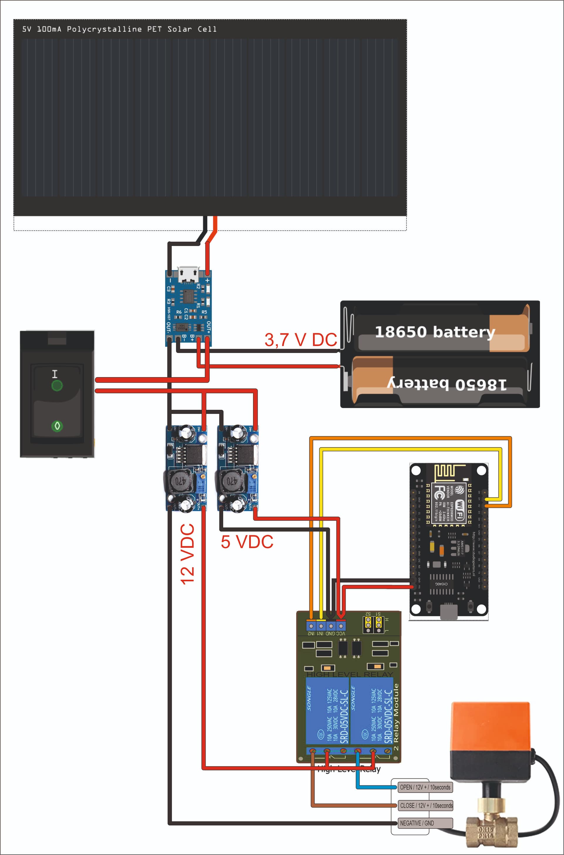
The times that I have set are the minimum necessary to record the short video and to see a first functional test. I am aware that for a section of time, it lasts a single day, I have to multiply the milliseconds, but this has been the reason for uploading my project to the forum, and asking for help. I want to know if there is any programming formula for whole days, simpler than not using milliseconds for one day. The motorized valve works with a small 12 V dc motor, there are three cables, one is ground, another is +12 V dc for opening, and the third cable is +12 dc for closing, and both closing and opening, the The motor takes about 10 seconds to complete, to make sure I have set 15 seconds of 12Vdc power for both opening and closing. I'll post a schematic of the circuit I'm building later. The first thing I have set in the program is, because it activated the two relays at the same time, with the possibility that the control pcb inside the motorized valve might burn. To get 12VDC from 18650 batteries, I have put a step-up booster power supply pcb, which works perfectly for me at the moment. Both the valve and the waterproof box with the solar panel and the whole set, I want to have it in the middle of the field in a place where the electric current does not reach. It is what makes it interesting, and above all, very cheap. I know that there are programmers with tubes included with batteries, but I think that the programming possibilities of working with ESP8266 are almost infinite, and I am entering this world of programming, and it is my first project in this regard.
I would write a function that delays for a variable number of hours. The number of hours would be passed to the function as a parameter.
You could then call the function saying you wanted it to delay for 24 hours (1 day) or 48 hours (2 days) and so on.
If you really want you could write a function that delays for a variable number of days, it would then call your hour delay function which would call the millisecond delay funtion.
This all seems a bit of an over kill . If you just used a valve and ball cock ( as per toilets ) , it will keep your tank full without any hassle .
If you want at a particular time of time of day use a solenoid valve and a time switch .
With projects like this it is worth looking at maintenance , complexity and reliability . Arduino isn’t the right path always for every job
In the absence of a time reference such as an RTC or an internet time source using WiFi, you have to relay on the accuracy of the clock source of the ESP8266. Whether you use millis() directly, or a software based RTC that lets you reference actual hours/minutes/seconds will make no difference in the accuracy. You will almost certainly gain/lose a few seconds each day, but unless you intend to run the system continuously for several years that should not be a problem in this application.
One major problem with not having an actual time reference is how to handle an unexpected processor reset or a power loss, because there is no way to know how long it has been since the last time the pump ran.
I repeat again, it is a first project, if the tree does not let you see the forest, it is your problem. Starting from doing a first project, I can control multiple valves, at more convenient times of the day with humidity sensors, rain sensors, tank level sensors. Things that a toilet valve does not let you do, esp8266 is worth it for this, to evolve and progress. Anyhow my opinion
But your original specification makes no mention of expanding the system - that may well change the whole approach to the project and should be mentioned at the start as it will affect the answers you get .
If you show me a lone tree , do you expect me to see a forest ?
Try not to ruffle feathers at this early stage .
You could make it impossible to power the opening and closing connections simultaneously by rearranging the relays. Wire the 1st relay with 12V to COM, then connect NO of this relay to COM of the 2nd relay. The motor wires for OPENING and CLOSING would be wired to the NC and NO contacts of the 2nd relay. To run the motor, first use the 2nd relay to select either the OPENING or CLOSING connection, then activate the 1st relay to provide the power.