Coding Glitch

I wrote some codes no matter which way I arrange them its not working the correct way.

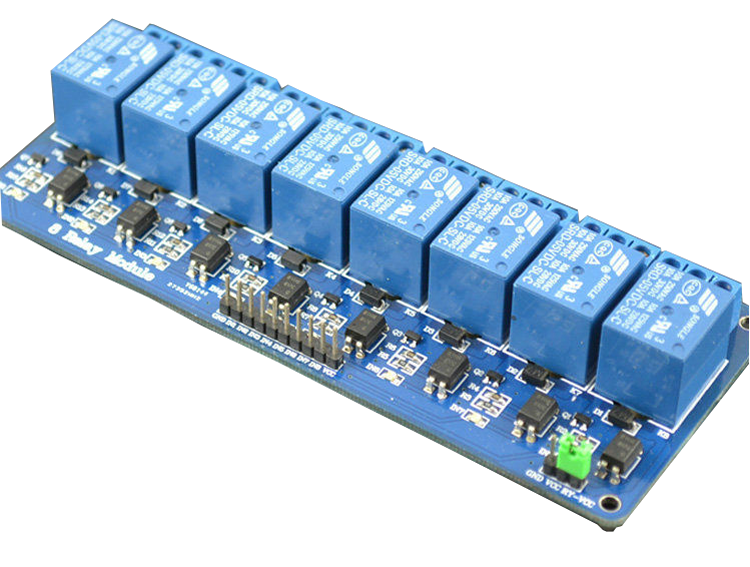
I programmed a mega to turn on 7 relays on a 8 channel relay board but when the relays are to be on they are off instead and vice versa.

here is the code

const int trigPin1 = 2;
const int echoPin1 = 3;
const int trigPin2 = 4;
const int echoPin2 = 5;
const int trigPin3 = 6;
const int echoPin3 = 7;

int sourcepump1 = 9;
int sourcepump2 = 10;
int transferpump1 = 29;
int transferpump2 = 33;
int ozonepump = 11;
int uvlamp1 = 13;
int uvlamp2 = 12;

int distanceInch1;
int distanceInch2;
int distanceInch3;
//int maxDistant = 88;
//int minDistant = 12;
int threshhold = 12;
int delayprint = 1500;


void setup() {
  Serial.begin(115200);
  pinMode(trigPin1, OUTPUT);
  pinMode(echoPin1, INPUT);
  pinMode(trigPin2, OUTPUT);
  pinMode(echoPin2, INPUT);
  pinMode(trigPin3, OUTPUT);
  pinMode(echoPin3, INPUT);
  pinMode(uvlamp1, OUTPUT);
  pinMode(uvlamp2, OUTPUT);
  pinMode(ozonepump, OUTPUT);
  pinMode(transferpump1, OUTPUT);
  pinMode(transferpump2, OUTPUT);
  pinMode(sourcepump1, OUTPUT);
  pinMode(sourcepump2, OUTPUT);
 
}

void loop() {
  long duration1;
  digitalWrite(trigPin1, LOW);  // Added this line
  delayMicroseconds(5); // Added this line
  digitalWrite(trigPin1, HIGH);
  delayMicroseconds(10); // Added this line
  digitalWrite(trigPin1, LOW);
  duration1 = pulseIn(echoPin1, HIGH);
  distanceInch1 = (duration1 / 2) / 74;
  Serial.print("ozone tank ");
Serial.println(distanceInch1);
delay(delayprint);

if (distanceInch1  > threshhold) {
  digitalWrite(sourcepump1, HIGH);
  digitalWrite(uvlamp1, HIGH);
  digitalWrite(sourcepump2, HIGH);
  digitalWrite(uvlamp2, HIGH);
}
else
{
  digitalWrite(sourcepump1, LOW);
  digitalWrite(uvlamp1, LOW);
  digitalWrite(sourcepump2, LOW);
  digitalWrite(uvlamp2, LOW);
}

long duration2;
digitalWrite(trigPin2, LOW);  // Added this line
delayMicroseconds(5); // Added this line
digitalWrite(trigPin2, HIGH);
delayMicroseconds(10); // Added this line
digitalWrite(trigPin2, LOW);
duration2 = pulseIn(echoPin2, HIGH);
distanceInch2 = (duration2 / 2) / 74;
Serial.print("pre treatment tank ");
Serial.println(distanceInch2);
delay(delayprint);

if (distanceInch2 > threshhold) {
  digitalWrite(ozonepump, HIGH);
}

else {
  digitalWrite(ozonepump, LOW);
}

long duration3;
digitalWrite(trigPin3, LOW);  // Added this line
delayMicroseconds(5); // Added this line
digitalWrite(trigPin3, HIGH);
delayMicroseconds(10); // Added this line
digitalWrite(trigPin3, LOW);
duration3 = pulseIn(echoPin3, HIGH);
distanceInch3 = (duration3 / 2) / 74;
Serial.print("Filling tank ");
Serial.println(distanceInch3);
delay(delayprint);

  if (distanceInch3 > threshhold) 
{
  digitalWrite(transferpump1, HIGH);
  digitalWrite(transferpump2, HIGH);
}
else
{
  digitalWrite(transferpump1, LOW);
  digitalWrite(transferpump2, LOW);
}

}

When I read from the serial monitor the reading from all 3 sensors are above 20, 1 gives 20, the other 42, and the other 86 but yet all relays are off.

What could be casuing this?

It seems that you're saying that if you change all your write(xxx, HIGH) to write(xxx,LOW) and vice versa the code will be perfect. I.e. your relays are active LOW and not active HIGH as you assume. Many are.

Alternatively it may be possible to get the same effect by rewiring the relays but I can't tell since you've given no detail of the relays.

Steve

Indeed. some relay modules are configurable with a jumper even, as the picture in the OP here shows:

https://forum.arduino.cc/index.php?topic=487884.0

Did you ever check how the relay(s) actually worked before writing your current code?

A simple test sketch that sets (in setup) a pinMode and writes a high to the pin; is the relay on or off?

Most relay boards have normally open (NO) and normally closed (NC) contacts. Moving the output wires around can be a solution.

If the relay is activated when you drive the pin low, the below will make life a little easier; just demo code.

#define RELAY_ON LOW
const byte relayPin = 3;
void setup()
{
  // set pin as output
  pinMode(relayPin, OUTPUT);
  // switch relay on
  digitalWrite(relayPin, RELAY_ON);
  // wait a bit
  delay(5000);
  // switch relay off
  digitalWrite(relayPin, !RELAY_ON);
}

Attached is a pic of the board. Is it that the jumper on the board is for letting it activate the relay with a high or low signal?

sterretje:
Did you ever check how the relay(s) actually worked before writing your current code?

A simple test sketch that sets (in setup) a pinMode and writes a high to the pin; is the relay on or off?

Most relay boards have normally open (NO) and normally closed (NC) contacts. Moving the output wires around can be a solution.

If the relay is activated when you drive the pin low, the below will make life a little easier; just demo code.

#define RELAY_ON LOW

const byte relayPin = 3;
void setup()
{
  // set pin as output
  pinMode(relayPin, OUTPUT);
  // switch relay on
  digitalWrite(relayPin, RELAY_ON);
  // wait a bit
  delay(5000);
  // switch relay off
  digitalWrite(relayPin, !RELAY_ON);
}

The output of the relay is fine activating the relay would be the issue, based on the code what should digital write high isn't doing so it's writing low.

I had the max distant set to 88 and mindistwnt set to 12, stating that if a sensor greater than max distant then digital write high doesn't work, I have to state that it's less than max distant for it to write high and the distants were all above max distant

enzyb:
Attached is a pic of the board.

How to inline an image

enzyb:
Is it that the jumper on the board is for letting it activate the relay with a high or low signal?

No, those boards are active low. With that jumper off, you use a different power supply for the relay coils from the Arduino 5V which controls the relays. All the Arduino is doing is turning the leds in the relay modules opto-isolators off and on.

If you connect it as below, with the jumper off, you get electrical isolation between the relays and the Arduino:

D0upWXs_d.jpg

Based on that image it seems the board is been powered by the external power supply but also the Arduino since the 5v and gnd is still connected from the Arduino to it.

Ok I really had no idea it was powered low so that means I should have switched my high and low signals and left my greater than and less than signs.

I do have a greater issue though to how the code is written when the water reachs the level for pump to turn ofr, it's comes on and off a couples times and when it's loosing water and the pump is to turn on the pump comes on and off a couple times also, but I don't want that.

I need a tolerance for it to empty to that level before it comes on and stop the pump from turning on and off and when it fills up ur doesn't turn on and off rapidly.

enzyb:
Based on that image it seems the board is been powered by the external power supply but also the Arduino since the 5v and gnd is still connected from the Arduino to it.

Look again: the Arduino ground is explicitly excluded from the mix.

As I said:

All the Arduino is doing is turning the leds in the relay modules opto-isolators off and on.

So the relay coils are powered by the external supply, but controlled by the Arduino.

enzyb:
Ok I really had no idea it was powered low so that means I should have switched my high and low signals and left my greater than and less than signs.

Yes, that's what I said back in reply #1 which you seem to have ignored. Never mind, you got there eventually.

Steve

enzyb:
Based on that image it seems the board is been powered by the external power supply but also the Arduino since the 5v and gnd is still connected from the Arduino to it.

No, definitely not, that's the whole point of these modules to provide isolation. Vcc and JD-Vcc are completely separate - the Arduino talks only to the opto isolator inputs when connected this way.

MarkT:
No, definitely not, that's the whole point of these modules to provide isolation. Vcc and JD-Vcc are completely separate - the Arduino talks only to the opto isolator inputs when connected this way.

Currently I am using the Arduino to power that board so it's best I use a external power supply?

Also if I remove the jumper and use an external power supply I should still use the 5v from the Arduino to it's vcc? Why though?

The ground from the relay board would that only come from the external PSU?

enzyb:
Currently I am using the Arduino to power that board so it's best I use a external power supply?

If you want electrical isolation between the relay itself (that is, the blue cube, not the relay module) you have to. Also, with 8 relays (datasheet), if you have them all energised at once that's going to be almost 600mA total, which is starting to treat the Arduino a power supply, which it's not.

enzyb:
Also if I remove the jumper and use an external power supply I should still use the 5v from the Arduino to it's vcc? Why though?

What controls the relay, is an led inside an opto-isolator on the module: you need to turn that led off and on. The Arduino 5V to the relay module Vcc is the +ve side of the led; the Arduino digital pin is the cathode. So when the digital pin is low, the led is on (5V on its anode, 0V on its cathode.)

When the led in the isolator is on (Arduino pin is low), the transistor in the isolator conducts, and the circuit energising the relay from its 5V supply (either the Arduino if jumper on, external if jumper off) is complete and the relay energises. (That explains why the Arduino pin needs to be low to energise the relay.)

enzyb:
The ground from the relay board would that only come from the external PSU?

Yes, if the jumper's off. If the jumper's on, you need the Arduino ground as the low side of the relay coil circuit.

OK thanks for the info.

The other issue I have is with the coding, it's working to a level where it will turn the pumps on and off but there is alot of on and off when it reaches the level where it should turn off it comes on and off repeatedly before it settles and that's not good.

Is there a way to fix that in a way that when it reaches the high or low level there is only one switching that takes place?

Search for "hysteresis". That's what you need. E.g. make the switch ON threshold different from the switch OFF threshold so the pump starts when it gets to 12 but doesn't stop until it gets down to say 11.

Steve

I have modified the code with a toplevel and a lowlevel but it doesnt recognise the low level section of the code, once the water goes below the high level the pumps start.

Currently I have the top level set to 20" from the top of the tank and the Low level set to 75 inches from the top of the tank. When the water reaches the top of the tank the pumps turn off even though its still flickering between on and off for a long while before it finally stops, but I am expecting the pump to only start again when it reaches 75" or more.

const int trigPin1 = 2;
const int echoPin1 = 3;
const int trigPin2 = 4;
const int echoPin2 = 5;
const int trigPin3 = 6;
const int echoPin3 = 7;

int sourcepump1 = 9;
int sourcepump2 = 10;
int transferpump1 = 29;
int transferpump2 = 33;
int ozonepump = 11;
int uvlamp1 = 13;
int uvlamp2 = 12;

int distanceInch1;
int distanceInch2;
int distanceInch3;
int topLevel = 20; // to turn the pump off
int lowLevel = 75; // to turn the pump on
int delayprint = 9000;
int writedelay = 2000;


void setup() {
  Serial.begin(115200);
  pinMode(trigPin1, OUTPUT);
  pinMode(echoPin1, INPUT);
  pinMode(trigPin2, OUTPUT);
  pinMode(echoPin2, INPUT);
  pinMode(trigPin3, OUTPUT);
  pinMode(echoPin3, INPUT);
  pinMode(uvlamp1, OUTPUT);
  pinMode(uvlamp2, OUTPUT);
  pinMode(ozonepump, OUTPUT);
  pinMode(transferpump1, OUTPUT);
  pinMode(transferpump2, OUTPUT);
  pinMode(sourcepump1, OUTPUT);
  pinMode(sourcepump2, OUTPUT);
 
}

void loop() {
  long duration1;
  digitalWrite(trigPin1, LOW);  // Added this line
  delayMicroseconds(5); // Added this line
  digitalWrite(trigPin1, HIGH);
  delayMicroseconds(10); // Added this line
  digitalWrite(trigPin1, LOW);
  duration1 = pulseIn(echoPin1, HIGH);
  distanceInch1 = (duration1 / 2) / 74;
  Serial.print("ozone tank ");
Serial.println(distanceInch1);
delay(delayprint);

if (distanceInch1 >= topLevel) {
  digitalWrite(ozonepump, LOW);
}

else if (distanceInch1 <= lowLevel)
{
  digitalWrite(ozonepump, HIGH);
 // delay (writedelay);
}
 

long duration2;
digitalWrite(trigPin2, LOW);  // Added this line
delayMicroseconds(5); // Added this line
digitalWrite(trigPin2, HIGH);
delayMicroseconds(10); // Added this line
digitalWrite(trigPin2, LOW);
duration2 = pulseIn(echoPin2, HIGH);
distanceInch2 = (duration2 / 2) / 74;
Serial.print("pre treatment tank ");
Serial.println(distanceInch2);
delay(delayprint);

if (distanceInch2  >= topLevel) {
  digitalWrite(sourcepump1, LOW);
  digitalWrite(uvlamp1, LOW);
  digitalWrite(sourcepump2, LOW);
  digitalWrite(uvlamp2, LOW);
}
else if (distanceInch2 <= lowLevel)
{
  digitalWrite(sourcepump1, HIGH);
  digitalWrite(uvlamp1, HIGH);
  digitalWrite(sourcepump2, HIGH);
  digitalWrite(uvlamp2, HIGH);
  //delay (writedelay);


long duration3;
digitalWrite(trigPin3, LOW);  // Added this line
delayMicroseconds(5); // Added this line
digitalWrite(trigPin3, HIGH);
delayMicroseconds(10); // Added this line
digitalWrite(trigPin3, LOW);
duration3 = pulseIn(echoPin3, HIGH);
distanceInch3 = (duration3 / 2) / 74;
Serial.print("Filling tank ");
Serial.println(distanceInch3);
delay(delayprint);

 if (distanceInch3 >= topLevel) 
{
  
  digitalWrite(transferpump1, LOW);
  digitalWrite(transferpump2, LOW);
}
else if (distanceInch3 <= lowLevel)
{
  digitalWrite(transferpump1, HIGH);
  digitalWrite(transferpump2, HIGH);
  //delay (writedelay);
}

}

}

I still need help with the flicking on and off also.

I made a change to the code wondering if this is the fix to the issues i have been having

const int trigPin1 = 2;
const int echoPin1 = 3;
const int trigPin2 = 4;
const int echoPin2 = 5;
const int trigPin3 = 6;
const int echoPin3 = 7;

int sourcepump1 = 9;
int sourcepump2 = 10;
int transferpump1 = 29;
int transferpump2 = 33;
int ozonepump = 11;
int uvlamp1 = 13;
int uvlamp2 = 12;

int distanceInch1;
int distanceInch2;
int distanceInch3;
int startPump = 40; // to turn the pump off
int tankFull = 20; // to turn the pump on
int delayprint = 9000;
int writedelay = 2000;


void setup() {
  Serial.begin(115200);
  pinMode(trigPin1, OUTPUT);
  pinMode(echoPin1, INPUT);
  pinMode(trigPin2, OUTPUT);
  pinMode(echoPin2, INPUT);
  pinMode(trigPin3, OUTPUT);
  pinMode(echoPin3, INPUT);
  pinMode(uvlamp1, OUTPUT);
  pinMode(uvlamp2, OUTPUT);
  pinMode(ozonepump, OUTPUT);
  pinMode(transferpump1, OUTPUT);
  pinMode(transferpump2, OUTPUT);
  pinMode(sourcepump1, OUTPUT);
  pinMode(sourcepump2, OUTPUT);
 
}

void loop() {
  long duration1;
  digitalWrite(trigPin1, LOW);  // Added this line
  delayMicroseconds(5); // Added this line
  digitalWrite(trigPin1, HIGH);
  delayMicroseconds(10); // Added this line
  digitalWrite(trigPin1, LOW);
  duration1 = pulseIn(echoPin1, HIGH);
  distanceInch1 = (duration1 / 2) / 74;
  Serial.print("ozone tank ");
Serial.println(distanceInch1);
delay(delayprint);

if (distanceInch1 > startPump - 5 || startPump + 5) {
  digitalWrite(ozonepump, LOW); // relay switches on Low
}

else if (distanceInch1 <= tankFull + 5 || tankFull - 5)
{
  digitalWrite(ozonepump, HIGH); //Relay switches off high
 // delay (writedelay);
}

You are not doing your comparisons properly

  if (distanceInch1 > startPump - 5 || startPump + 5) {

That code does NOT compare distanceInch1 to startPump +/- 5. It compares distanceInch1 to startPump -5 OR it just evaluates startPump+5 which will always be true since startPump is 40.

You need to include the comparison twice

  if (distanceInch1 > startPump - 5 || (distanceInch1 < startPump + 5)) {

to test for distanceInch1 between 35-45. Same for the tankFull if(). BTW, that is not how you would normally implement hysteresis so you pumps don't cycle. It would be more like

if (distanceInch1 > startPump ) {
  // start pump
}
if (distanceInch1 < startPump - 5) {
  // turn pump off
}
[code] rather than combining them into a compound if() statement.

thanks for the update but I dont want the pump to restart immediately after it goes below the point that it turns off. I need the tank to reach about half or a little below before it starts and then I need both to happen without the pump flickering on and off when it reaches the low or high set points of and on off.

if (distanceInch1 > startPump + 5) {
  digitalWrite(ozonepump, LOW); // relay switches on Low
}

if (distanceInch1 < startPump - 20)
{
  digitalWrite(ozonepump, HIGH); //Relay switches off high
 // delay (writedelay);
}

In this case if the water level is between 40 - 45 the pump will start and it should fill until it reaches 20? or will it still sense the startpump which is set to 40 and stop or will it go all the way to 20 and stop? This is the part I dont understand.