As the title says, I need to design a "one to rule them all" matrix driver, where independent if the matrix has a common anode or common cathode configuration, by code it should be able to control it.
Some characteristics:
Forward current up to 30mA
very high ohmic lines (max voltage can reach up to 12 Volts)
There are two TMUX6208 which are 8:1 bidirectional mux/demux, their purpose is to select the row/column. Then the MAX20327 since is just a pair of spdt switches will define the current flow.
This is my broad idea so far, and it lacks a lot. I don't know/ haven't thought if either I should place a current source, or I should sink it.
There could be a component that already does this job and I haven't seen it.
As you are only going to be driving 1 LED at a time, those 30mA capable muxes should work.
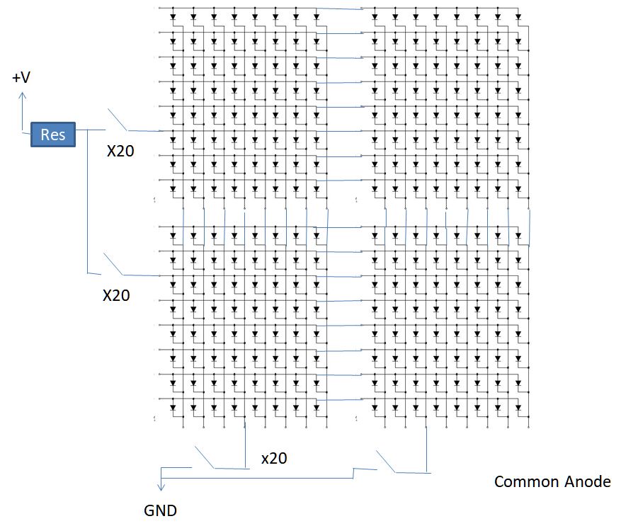
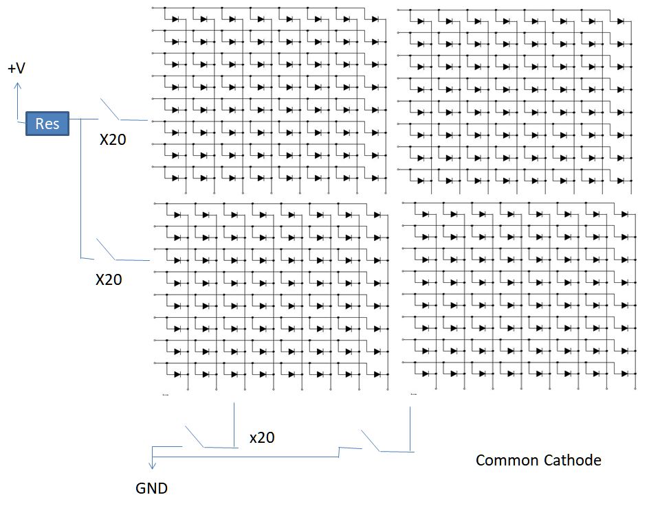
As you can see in the attached, there is really no difference between Common Anode & Common Cathode matrixes. It's just a matter of how you wire them up.
I used the schematic from a common anode & common cathode display to show that.
If you are planning to multiplex this display to give the appearance of more than 1 LED being on at the same time,
that might end up appearing as a dim overall display, with just 1 of 400 LEDs being on at any one time.
With 30 frames a second refresh rate = 33.3ms, split over 400 LEDs = 0.08325 mS on time for each LED, which may not even be viewable.
Are you seriously suggesting that of the whole 20 by 20 display, you only ever want one LED to be seen?
Because that is the limitation that using multiplexers for both rows and columns would have.
That is not the same as a multiplexed display where you are producing the appearance of any number, even all of the LEDs being lit by sequentially lighting groups of LEDs in rapid succession. The group is all desired LEDs in a single column or row, and you sequence through the corresponding columns or rows so that the proportion of the time a given LED is lit is divided by the number of columns or rows, 20 in your case.
Now lighting each LED for one twentieth of the time is doable, albeit not very efficient. Lighting each LED for merely one four-hundredth of the time clearly is not, so if you thought you were going to make a full image that way, you will be sorely disappointed.
If you are certain you want only 1 led on at a time, simply use 5x 74hc595. The pins of this chip can source or sink 30mA. There is a 70mA overall current limitation per chip, but that should not be a problem, even of the same chip is sourcing 30mA and sinking 30mA. You will need 20 series resistors.