AI has provided me the following English translation:
"I thought one of them was faulty, so I made the same connection to the other JDY-40."
There will be more than one JDY-40 module pair in the environment. Can a healthy transmission be achieved without addressing the modules with the AT configuration?
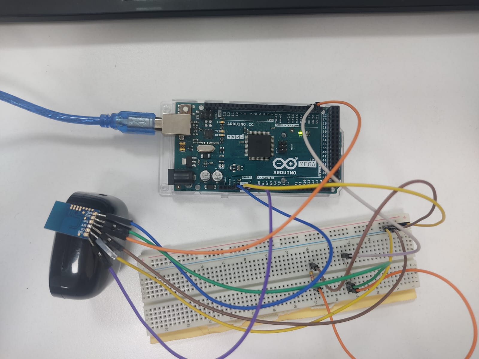
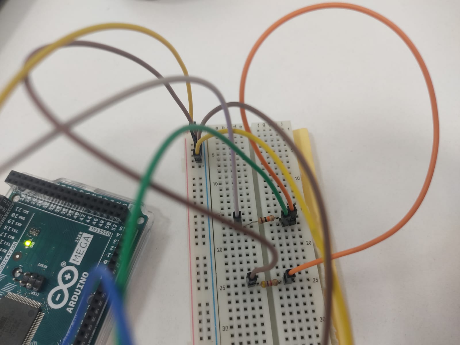
Here are my connections. I can't get a response. I made a voltage divider for the Arduino mega RX pin. (With 10k and 4.7k resistors)
void setup() {
  // Start communication with the Serial Monitor (PC)
  Serial.begin(9600);
  // Start communication between JDY-40 and Arduino Mega (Serial1)
  Serial1.begin(9600);  // Mega's hardware serial port (TX1 and RX1)

  Serial.println("Ready to send AT commands to JDY-40...");
}

void loop() {
  // Send AT commands from the Serial Monitor to JDY-40
  if (Serial.available()) {
    String command = Serial.readStringUntil('\n'); // Read the command until a newline
    Serial1.print(command);  // Send the command to JDY-40
    Serial1.print("\r\n");   // Add a newline (CRLF)

    // Show the sent command in the Serial Monitor
    Serial.println("Sent AT command: " + command);
  }

  // Print the response from JDY-40 to the Serial Monitor
  if (Serial1.available()) {
    String response = Serial1.readStringUntil('\n');  // Read the response
    Serial.println("Response from JDY-40: " + response);
  }
}


Note the similarities. Which is to say: could you please post a schematic or wiring diagram of your setup to go with the photos? Photos generally help fill in the possible gaps that a schematic may leave.
I don't think so
By the way

Are these pins soldered or not? Why not to solder a standard pins header instead this?
pins soldered
@melloisa
I have JDY40 modules, I use them to output diagnostic messages in cases where the board cannot be connected to USB with wires.
I have not experienced any problems in switching these modules in AT mode.
I think you have problems with the physical connection. Your soldering does not look very reliable. In addition, the pin headers on the Mega also often have poor contact with the wires
@melloisa
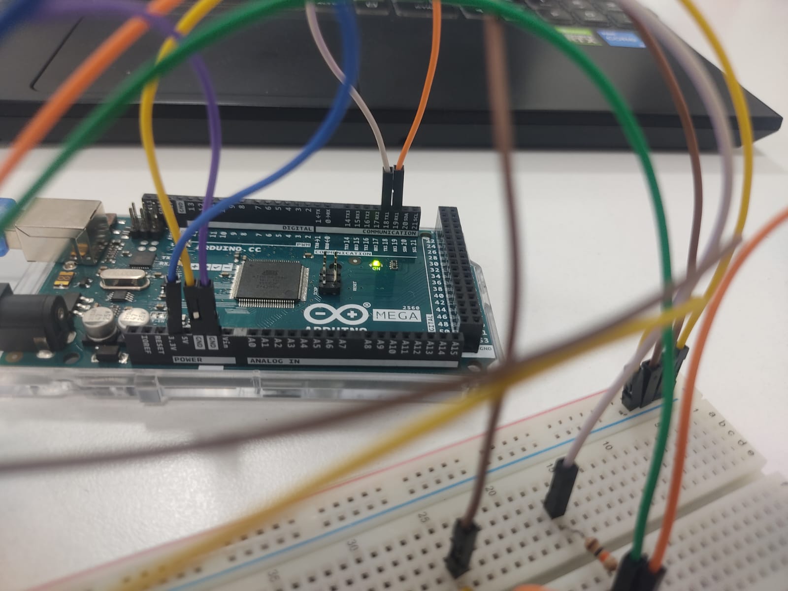
You were asked to show a photo to check the correctness of the connections. But your pictures do not allow this to be done, because they do not show the numbers of the Mega pins where the wires are connected.
In addition, the colors of the wires are also usually chosen not by chance, but taking into account certain rules. Usually, the power "plus" (VCC) is chosen in red, and the GND is black or brown. Both of your power wires are blue - this increases confusion
Where is 'command' set? I.e. where's the rest of your sketch?
Which terminal do you use when performing AT configuration on the modules?
I only entered 3.3V/ GND/ TX1/ RX1 pins on the Mega with a jumper cable.
Apart from that, my connections are already
VCC >>3.3V
GND>>GND
Rx>> Voltage divider and Tx (mega's TX>10k>JDY-40 Rx)(mega's TX>10k>4.7k>GND)
Tx>> Rx
CS>>GND like this.
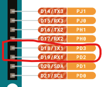
Stepping aside the incorrect nomenclature for the Arduino pins (I assume you mean "TX1" and "RX1" instead of "Tx" and "Rx") - can you confirm this is connected to the correct pins:

Which pins does Serial1 in your sketch align with on the Mega board?
As said before:
There's still no wiring diagram, which would clarify this issue.
I think you need to pay attention to details more. Sloppiness doesn't jive well with embedded systems engineering.
This topic was automatically closed 180 days after the last reply. New replies are no longer allowed.