Hey guys
I am using an Arduino MKR GSM 1400 (Atmel SAMD21)
I want to use Pin PA07 as PWM pin, on the data sheet it says it is possible but sadly the core arduino libray doesnt support it by default.
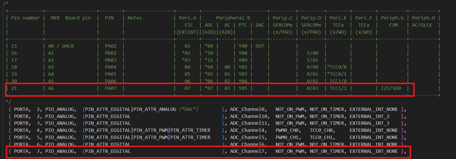
I did confirm the pin is connected and to PWM channel by changing the variant like this -
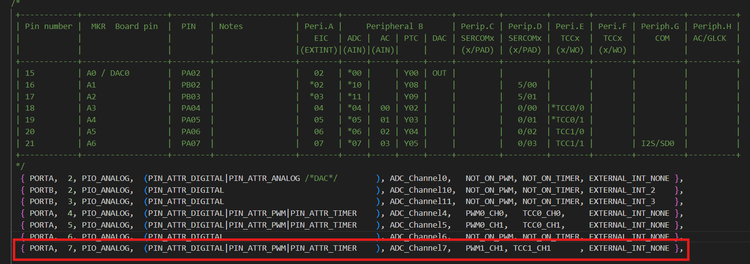
I now want to opreate the pin as PWM with the original variant so I tried to run this sketch (Chat GPT wrote most of it)
void setup() {
  Serial.begin(9600);
  // Step 1: Set PA07 (Pin 21 in your variant) as output
  PORT->Group[PORTA].DIRSET.reg = PORT_PA07;  // Set PA07 as output

  // Step 2: Connect PA07 to the TCC1 peripheral using the pin multiplexer
  PORT->Group[0].PMUX[7 >> 1].bit.PMUXO = PORT_PMUX_PMUXO_E;  // Select function 'E' for TCC1/WO[1] (PA07 is odd)
  PORT->Group[0].PINCFG[7].bit.PMUXEN = 1;  // Enable the peripheral mux

  // Step 3: Enable the clock for TCC1
  GCLK->CLKCTRL.reg = GCLK_CLKCTRL_ID(GCM_TCC0_TCC1) |  // Select TCC0 and TCC1
                      GCLK_CLKCTRL_GEN_GCLK0 |          // Use GCLK0 as the clock source
                      GCLK_CLKCTRL_CLKEN;               // Enable the clock
  while (GCLK->STATUS.bit.SYNCBUSY);  // Wait for synchronization

  // Step 4: Configure TCC1 for PWM
  TCC1->CTRLA.reg = TCC_CTRLA_PRESCALER_DIV64 |  // Set prescaler to 64
                    TCC_CTRLA_ENABLE;            // Enable TCC1
  while (TCC1->SYNCBUSY.bit.ENABLE);  // Wait for synchronization

  TCC1->WAVE.reg = TCC_WAVE_WAVEGEN_NPWM;  // Set TCC1 to normal PWM mode
  while (TCC1->SYNCBUSY.bit.WAVE);  // Wait for synchronization

  // Step 5: Set the period and duty cycle
  TCC1->PER.reg = 255;  // Set period (for 8-bit PWM)
  while (TCC1->SYNCBUSY.bit.PER);  // Wait for synchronization

  TCC1->CC[1].reg = 127;  // Set duty cycle to 50% on TCC1 Channel 1
  while (TCC1->SYNCBUSY.bit.CC1);  // Wait for synchronization

  // Enable the output for PWM
  TCC1->CTRLBSET.reg = TCC_CTRLBSET_DIR;  // Set direction (optional for PWM)
}

void loop() {
  Serial.println("Alive");
  // Optionally adjust the duty cycle dynamically in the loop
  delay(1000);
  TCC1->CC[1].reg = 64;  // Change duty cycle to 25%
  while (TCC1->SYNCBUSY.bit.CC1);  // Wait for synchronization

  delay(1000);
  TCC1->CC[1].reg = 192;  // Change duty cycle to 75%
  while (TCC1->SYNCBUSY.bit.CC1);  // Wait for synchronization
}
It doesnt work of course.
Does anyone knows why it doenst work?