When connecting an LED to an ESP32, where is the best position for the current-limiting resistor — on the anode (between the GPIO pin and LED) or the cathode (between the LED and GND)? Are there any advantages or differences between these two configurations in terms of performance or safety?
I consider using either lead the same.
If you think there's a chance you might accidentally touch one of the LED pins with a stray ground, then the resistor should be closest to the GPIO side.
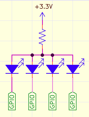
Thank you All for your feedback. I forgot to add that I have 10 LEDs that I have to control separately and only 1 LED will be switched ON each time. I wonder if I can use only 1 resistor between all LEDs and their GND (see below)
GPIO1 ----|>---- LED1 ----|
GPIO2 ----|>---- LED2 ----|
GPIO3 ----|>---- LED3 ----|
GPIO4 ----|>---- LED4 ----|----[R]---- GND
GPIO5 ----|>---- LED5 ----|
GPIO6 ----|>---- LED6 ----|
GPIO7 ----|>---- LED7 ----|
GPIO8 ----|>---- LED8 ----|
GPIO9 ----|>---- LED9 ----|
GPIO10 ---|>---- LED10 ---|
This is the conventional way to use an LED.
You use the GPIO as a current sink.
To turn on the LED you set the output LOW.
Yes you can use one resistor.
Red and Green work OK on an ESP but some Blue may not work.
In the case you have mentioned, i.e. only one led at any one time is switched on, then you can do this. If, however, multiple leds can be on simultaneously, then the brightness changes depending on how many leds are currently on. This may not be desirable.