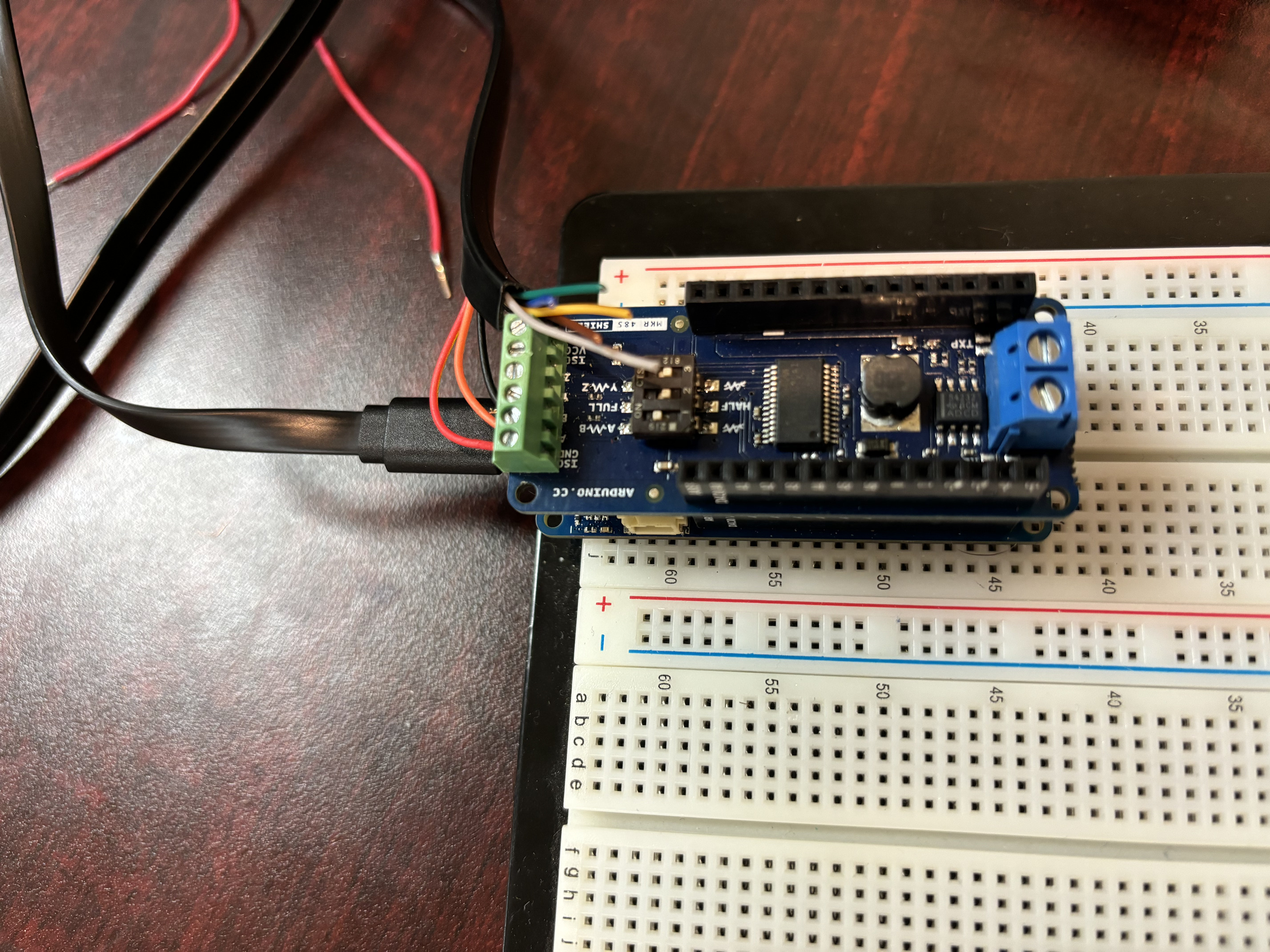
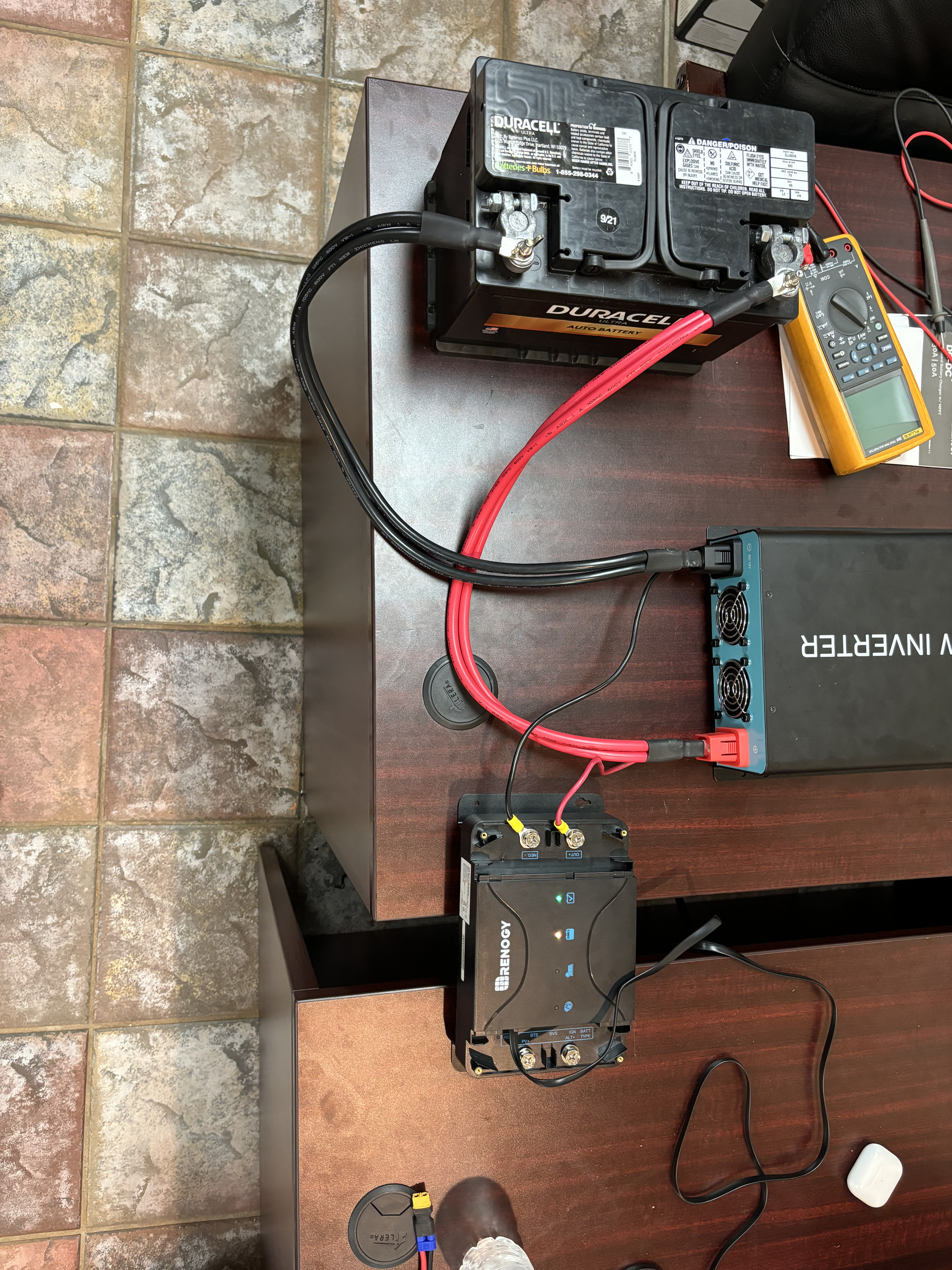
I am trying to pull information from the Renogy DC-DC Battery Charger via RS485 and Modbus communication. I am using the Arduino MKR WIFI 1010 and the Arduino MKR 485 Shield with it. In order to communicate I am using a RJ45 cable. My problem is when I run my code (Attached below), I get an error message saying, "Connection timed out." Does anyone have any fixes?
#include "ArduinoRS485.h"
#include "ArduinoModbus.h"

float voltage;

void setup() {
  Serial.begin(9600);

  delay(1500);

  if (!ModbusRTUClient.begin(9600)) {
    Serial.println("- Failed to start Modbus RTU Client!");
    while (1);
  }
}

void loop() {
  voltage = readVoltage();
  Serial.print("Battery Voltage: ");
  Serial.print(voltage);
  Serial.println(" V");
  delay(3000); // Delay 1 second between readings
}

float readVoltage() {
  float voltage = 0.0;
  // Send reading request over RS485 to address 0x01 and register 0x0101 (example)
  if (!ModbusRTUClient.requestFrom(0x01, INPUT_REGISTERS, 0x0101, 1)) {
    // Error handling
    Serial.print("- Failed to read the voltage! Error: ");
    Serial.println(ModbusRTUClient.lastError());
  } else {
    // Response handler
    uint16_t highWord = ModbusRTUClient.read();
    uint16_t lowWord = ModbusRTUClient.read();
    uint32_t millivolt = (highWord << 16) | lowWord; // Combine high and low words
    voltage = millivolt / 1000.0; // Convert millivolts to volts
  }
  return voltage;
}