Continuation on bidirectional rotation counter

I will try and answer the recent questions:

gcjr

but would you mind providing a more succinct description of what you're trying to do ... rather than how you think to do it.

... looking over the code, what doesn't it do that you want?

As I alluded to earlier, the first big obstacle I kept facing was the chaotic output from the sensors. I attributed this to coding but it may be that the type of sensor or placement relative to each other is causing misreading and miscalculation of direction and thus net count.

I also could not manage to transition from the working Uno sketch to the ESP2866 or ESP32 S3 without the coding for the counting process getting all messed up. I also could not get the BLE on ESP32 S3 to work.

I am asking for help in doing the following

  • Streamlining Code if deemed necessary

  • Advice on transitioning this sketch to one that will port to cellular phone by Bluetooth or Wi-Fi (if I can make Wi-Fi connect conveniently).

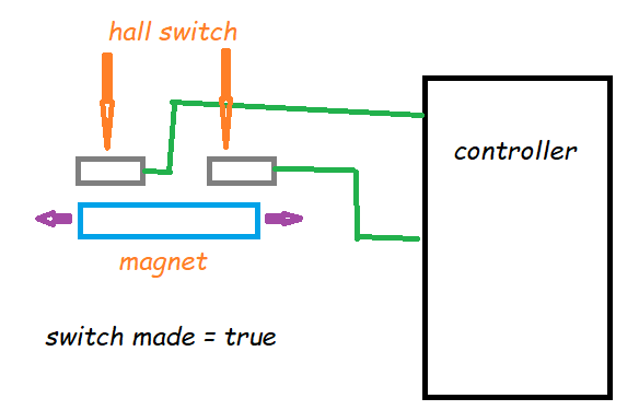
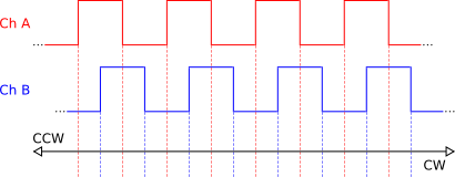
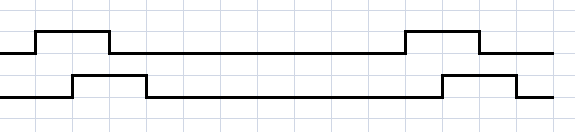
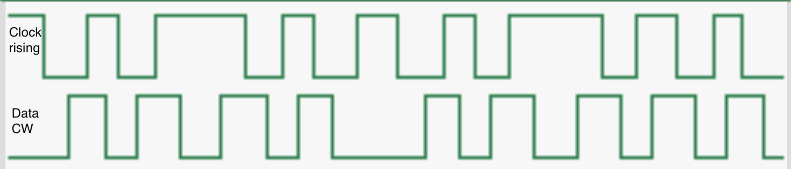
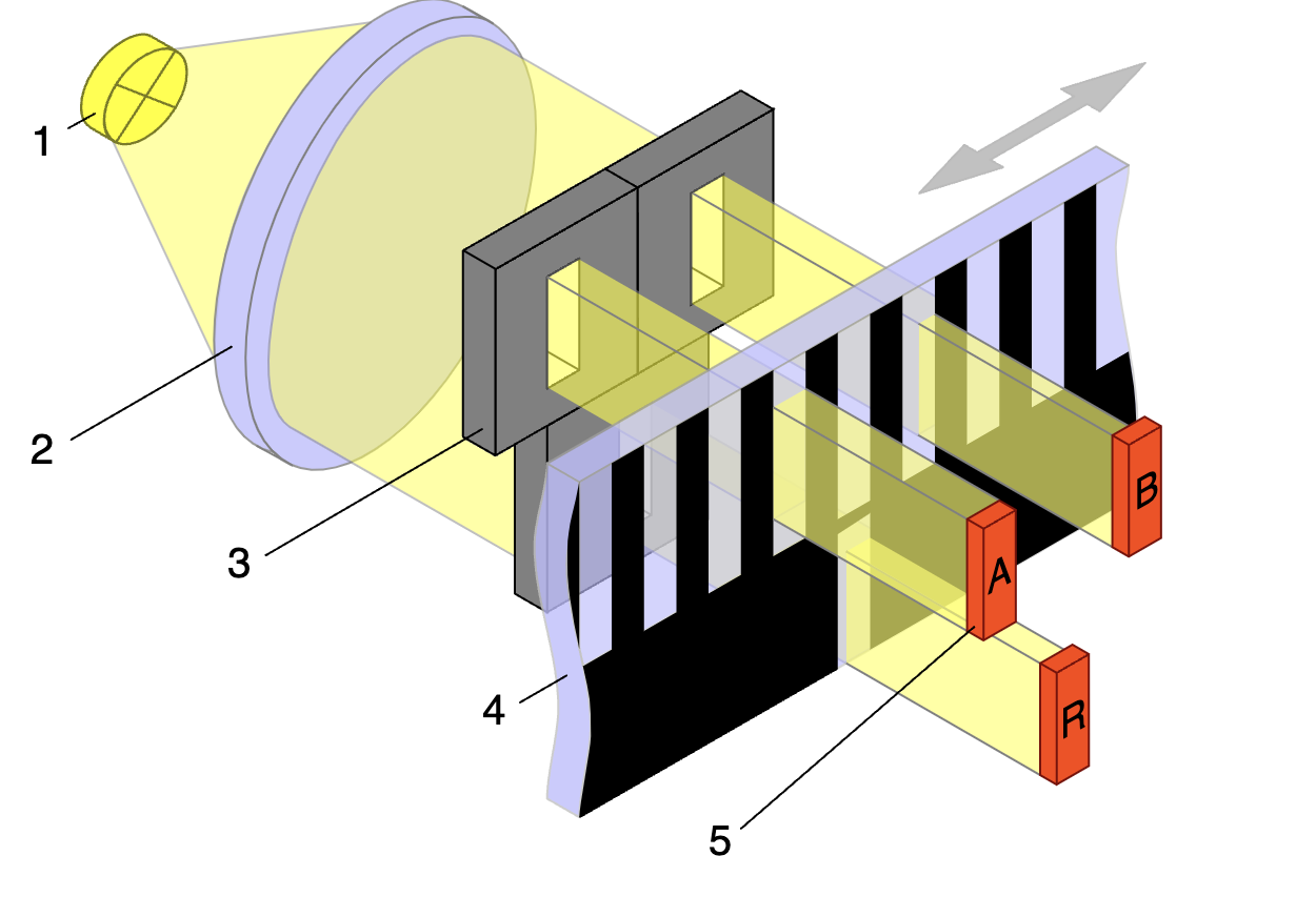
  • Advice on what is optimal arrangement for Hall Effect sensor setup. I didn’t completely understand optimal placement of sensors relative to each other. Some said they need to be far enough apart that one sends clearly after the other. Others seemed to suggest that they should be close enough that the High of one overlaps temporally with the Low of the other as appears on oscilloscopes. I am hoping someone knows about using Hall Effect sensors for determining rotational direction, or can refer me to someone who does. I was told to consider rotary encoders earlier but I don’t think this is possible as this apparatus does not have a spinning axil or a rotor surface conducive to this.

  • Advice on getting an android app to display the data. Also need to have two reset buttons, if possible, to reset each unit when needed.

  • Advice on which platform to use. The Uno is too limited in resources. I thought the ESP32 S3 would have adequate resources for processing and memory but I could not get the above sketches to work on this platform. I couldn't seem to even get the OLED, or Serial Monitor to work. Or the count processing would become completely erratic and unreliable. It looks like the ESP32 might also provide the wireless connection but I didn't want to buy another platform without trying to get help.

StefanL38

You seem to write to the EEPROM very (if often.
Are you aware of that the EEPROM will be worn out after 100 000 write cycles?

If you want to want to do 10^12 writings use a FRAM-module

I need to have the last count stored so if the phone or microprocessor powers off, it will display the last net count as this still indicates the current depth of the downrigger. On occasion, If the digital counter loses accuracy relative to the mechanical counter, they can periodically be resynched by the reset button when the mechanical counter is zeroed out.

I was aware that the EEPROM had limited write cycles but with all the current problems I figured I’d cross that difficulty if I ever get this running.

That FRAM-module looks like a good option.

StefanL38

Displaying
10CCW11____02CCW21
S1L S2H______S3H S4L

is not a selfpurpose
I would like to know what the finale purpose of displaying such numbers is

I’m sorry, working with these variables so much it seemed it was evident what they correlated with but I see now this is not clear.

Line 1: absolute rotational count (+and – rotations); direction CCW or CW; Net Count (CW count minus CCW count) for rotor 1 and 2

Line 2: the complementary sensor states in each pair for rotor 1 and 2

The real numbers of interest are the digits that follow the directional indicators, CW or CCW. In this 2.42 OLED display these are the large numbers indicating the net count of each rotor. This should indicate the current actual depth of the downrigger at any given time. (I had to write it in such a confusing manner because it’s the only way I could cram it into the 1602 limitations of the LCD.

This is how the data would appear when not constrained to the 1602 LCD display.

The 3 parameters in line 3 and 4 are used to backcheck the processing underlying the Net Count.

The absolute count can be checked with the mechanical digital counters. The direction should correlate with the sensor state indicators.

On a large display like a phone only the Net Counts would be emphasized and the other data could be in a very small box or eventually omitted if it proves accurate with use.

If I can get the data to the phone, I could use something like Remote XY though I’d prefer a subscription free option.

gcjr

i needed to change the partition to allocate more memory when i added Bluetooth to an esp32 application.

how frequent? how fast can your eye see a change? would once a second be adequate

I need to have frequent updates because in an urgent situation, like a sudden rocky obstacle, you see it coming in advance on the fish finder and need to know what the current count is and run back and raise the downrigger line if it's too low. You could hit something in 5-15 seconds depending on boat speed.

i've been working on an esp32 program that transmits a string with 3 acceleration and 3 gyro
6-digit values over broadcast UDP msg and am using a Java program to display them on a laptop. A string is sent every 100 msec.

wifi doesn't seem to need as much memory as Bluetooth

I would take whichever path I can get to work and is the easiest to connect with from the cell phone,

I missed this post. I can't use a computer on the boat with its limited space.

I'd like to get a demo-code to try the own accesspoint since I have 3 ESP32 S 3 modules. Does this allow you to enlarge the text on the phone or is a fixed pitch?

ESPUI uses a fixed font size
ESP Dash might have bigger fonts

If you use direct HTML you have control over the font-size.
Though me personal I have no exprience with HTML. Just using ESPUI and ESP Dash.
But if you start with whatever demo-code you will get support here

what is the problem? i ran the code with some buttons and saw counts from detectRotation() increasing and decreasing in value. Why are CCW events only counted if netCount1 > 0

i'm still unclear on what the sensors are detecting. And confused by if the comment is talking about individual sensors overlapping or the output for the two encoders -- each encoder has two hall sensors that need to overlap. Can you post a diagram

aren't all encoders rotary, measure shaft rotation

so within a second (e.g. not msec, usec)

detection needs to be fast enough but the display can be updated once/second

What is a demo-code, is it to just get the microprocessor up and running.

If I get this going and renew my efforts to get this sketch over to the ESP32 S3, or maybe switch to an ESP32, which I think has WiFi and both regular Bluetooth and BLE, do you think I can get help getting this sketch to work on that platform?

It is a rather short code that demonstrate the principle of any kind of application

  • reading in a sensor value
  • creating a small website
  • switching light patterns on RGBcolor-LED strings
  • rotating a stepper-motor
  • what ever the application might be

Back in post # 6 I posted a demo-code that uses the ESPUI-library to show what the ESPUI-library can do.

Ok things become clearer now

You are using your device on a rather small boat with no main-voltage supply
=> device is battery powered.

Not familiar with fishing terms. And you can't expected microcontroller fans to be fishing experts. What is a downrigger ?
Found this picture

So the main purpose of your microcontroller-device is to count rotations which correlate to how ddeep is the downrigger-weight below the watersurface.

You have a fishing sonar onboard that looks forward into drive-direction.
Whenever your fishing sonar detects obstacle ahead you need to wind up the downrigger weight nearer to watersurface to prevent the downrigger weight from getting caught.

This is the final purpose of it all.

These are the important details about the framework:

A boat you are on most of the time standing at the bow of the boat watching the fishing sonar. Fishing rod and downrigger are at the stern of the boat. The distance is about 3 m.

If an obstacle comes closer you have to run to the stern of he boat and wind up the downrigger-line.

You have to wind up within 5 to 15 seconds.

Well this description would have been very very good if you would have posted it in your very first post.

So updating the display 5 times per second seems to be sufficient.
Still additional technical data is nescessary to know.
Diameter of the real thing that rotates and serves to count rotation
distance how many meters you wind up the downrigger-line
time in which you wind up the downrigger-line this distance

So it will be possible to calculate rpm of the rotating thing and calculating the maximum frequency of the encoder pulses.

Knowing the real circumstances enables to make new suggestions how to achieve the final purpose:

two rather small displays both showing the same numbers one display near to the fishing sonar one display near to the manual downrigger winder.

Another option would be to have a wired or wireless remote control with two buttons up/down and a motor that does the winding. This would enable to wind up / down while standing at the bow of the boat watching the fishing-sonar by pressing the up/down-buttons.

And this enables a completely different solution:
depending on how much load the motor has to wind up/down a stepper-motor could be used. And with a stepper-motor you are already controlling rotations which means that no encoder is required at all.

Another option would be to use a servomotor which already has positional feedback inlcuded.

And as such a fishing equipment is not just a $20 hobby - I guess it is more in the range of $1000
You might be able to spend about $50 to buy such a ready to use shaft-encoder
https://www.01mechatronics.com/c/sensors/

Looking at the sensor photo in post 17 -


If you could add one or two additional magnets to effectively make one long magnet it might work like this:

And you'd get a quadrature type directional signal once per revolution.

YMMV

Yea! StephanL38 you figured it all out.

I never meant this to be so abstruse. I just didn't think it would be so difficult to determine the net count of basically a rotating wheel once direction can be determined. I thought this would be the same process for any "wheel" whether it was on a revolving spool like this or the model train wheel. One was translating rotations to fishing line and the other to the distance a train ran over tracks.

But now I see how I inadvertantly created a huge smoke screen over what I was trying to accomplish. I will respond in more detail in a bit but I am trying to find someone who can tell me exactly how the sensors should be situated relative to each other because tonight I was doing some trouble shooting, manually rotating the rotor, and realized that my interpretation of how the sensors should be positioned may be the major problem I have been confronting.

Does anyone on the forum possibly know someone who has technical experience or knowlege about using 2 individual Hall Effect Sensors to determine rotational direction of a spool or wheel ? (Not the highly complex modules made to indicate any number of parameters in modern automobile engines.) Such a resource would be a great help and possibly clear up the root source of all the confusion I have been experiencing.

why is this different that ny quadrature encoder, and it appears that yours works.

A common approach is to look for either a rising and falling transition on one input and then looking at the state of the other input to determine if the direciton and whether to inc/decrement a count

your approach is to look for a Low-to-High transition on either input AND that the other input is LOW to determine whether to inc/decrement a count. This approach may only work in your case if the AND condition is that the other input is HIGH instead of LOW

1 Like

Your description was really quite accurate for someone who knew nothing about downriggers. (See it was just a challenging puzzle for you solve!)

A few slight adjustments: My boat is 18 ft long and we sit in two seats about 2/3 way from stern to bow. When I said 5-15 seconds, I just was giving a general idea of how quickly a response time might be. It is quite variable, especially dependent on the speed of the boat and factors like wind and drift.

ADDITIONAL DATA:

Diameter of the spool: It is 7 inches across on the rim. But the inner hub has a circumference of 1 foot so each rotation is close to a foot in line length. It is a bit off because of the thickness of layers of line. But the line is .5 mm thick and it layers evenly over the 1.125 inch width hub, so even a hundred turns does not produce meaningful error for this purpose.

UPDATING FREQUENCY: I believe that for this digital count to synchronize with the mechanical counter on the unit, it would need to add or subtract each rotation. EXTENSION: The fastest speed is when the clutch is released and the lead ball drops in free fall. I videoed this from 0-100 ft and it took about 13 seconds. So, it’s about 7-8 rotations per second at maximum speed.

RETRACTION: It took about 31 seconds to actively retrieve the 100 feet of line at maximal rate. This is about 3 rotations per second.

LENGTH OF LINE EXTENDED: I don’t go beyond 100 feet as that’s about max for this lake. I usually am ranging from 20-60 depending on species of fish and their depth, and the underwater topography.

DISPLAYS: I would like to have data from both rotors displayed on a cell phone screen ideally , if I can keep the screen constantly on, (but on USB C cable when up on the dash). If I take it mobile, say when fishing on the bow, I would carry it with me. While it would be nice to have a larger display on the unit, if I am there already it’s probably simpler to just refer to the mechanical counter.

Theoretical ā€œImprovementsā€

I used to fish from a kayak on the ocean when younger, before settling on the RV at the lake. I made a small downrigger made by attaching a gearmotor to a large saltwater level wind reel. I powered this with a 12 volt gel cell battery and made a small 1x1.5 inch two way remote to control extension and retrieval. The remote was clamped to the midpoint of my kayak paddle so that I could easily control it as I paddled and watch the fish finder. I didn’t really use this because the battery source was a limiting factor. I had bought some lithium iron phosphate batteries (back when they were costly and not reliable) and the control boards never worked right. I used iron phosphate for safety because the battery was stowed within the plastic hull and I had vision of seeing the hull glow brightly just before sinking!

I had considered making a remote-controlled downrigger for the boat, but there are two basic types of downriggers. A bidirectional drive by Canon and a Retraction Drive only by Scotty. The spool of the Canon lies in the vertical plane and this caused a kind of bouncing action when the line dropped, which I don’t prefer. The Scotty spool is in the horizontal plane and doesn’t bounce. I has a clutch which allows smooth control and rapid of extension of the line, since an 8-10 pound lead ball drops through the water pretty quickly. But since the Scotty is only powered in one direction, it is not conducive to remote control.

It's important to understand load, and risks involved in pulling an 8-20 lb. ball if you were fishing at ocean depths. You might be at 200-400 ft and there is tremendous drag on the 150 lb. test cable as it pulls the weight through the water at up to 6-8 mph. You don’t want to just jury rig a mechanism that can’t withstand the physics. Last year my friend was trolling slowly at only 1 mph. His ball hung up and even though he was right near the downrigger, the tension was enough to just break the whole unit off its mount. If you’re not careful in design, you could also do serious damage to the gunnel, or side of the boat.

My Scottys are older and sell for about $700 each. So, it’s economical for me to create such an ā€œupgradeā€. The top of the line Cannons ($2000) can be networked to a Humminbird fish finder ($2500) and a Min Kota electric trolling motor ($2500) on the bow. This allows the fish finder microprocessor to control, speed/direction and automatically retract or extend the downrigger to a preset depth based on the fish finder readings. It can immediately raise the ball if needed and then relower it as the depth deepens again. I have neither the $ nor the life expectancy to make this a wise proposition.

I am having some confusion about how the sensors should be situated around the rotor. Most sources say they should be set at 90 degrees apart:

"The two Hall effect sensors should be positioned 90 degrees apart relative to each other around the rotor. This means that if you imagine the rotor as a clock face, one sensor would be at the 12 o'clock position and the other at the 3 o'clock position."

What confused me is that when I saw patterns like your Ch A Ch B on oscilloscopes it looked like the sensors needed to be close enough so that the HIGH from one was being read while the other was reading low. So, I thought this meant the sensors needed to be close together. That's probably a dumb conclusion, but since I was operating without any outside input, that's what I thought. My sensors are close together. So, last night I decided to reposition the magnets to be 90 degrees apart. That is not so simple because the support for the sensors has to be completely reconfigured. Anyway, in removing and reinstalling the sensors, I screwed something up so they are not being read now. I kept having the plastic covered pins fall out or become loose and so I tried to solder the wires to the pins and I think I damaged the module somehow. So, I can’t test the 90-degree arrangement until I can get new sensors. I will have to take a pause.

Regarding the "quadrature encoder" when someone referred to that at the very beginning of this thread, I looked it up and it seemed like I involved the use of specific encoding devices that either were attached or integrated into a revolving shaft. Or conducting strips as used in a potentiometer were embedded on the rotor or wheel. But these didn't seem plausible since this has no central axil that spins. Maybe it is a concept that refers to how the signal is being processed and would work with the two hall sensor model that I am using. Again, I just didn't know how the code for the quadrature encoder could work with the dual sensor approach as well.

Yes. The output from the graphic illustrating a longer magnet in post #28 should look like this:

rather than the square wave for a regular encoder. One set of quadrature signals per revolution. You still have the phase difference to sense direction.

1 Like

Can you give any additional details regarding how this should be set up? I thought you could have a single neodymium disc magnet on the rim of the rotor with the S side facing the sensor. The rotor turns and the hub is stationary. I have a startionary semi-circular stationary platform attached to the hub that holds the two Hall Effect modules with their chip facing outward so as to be passed overby the rotating magnet. I had placed the two modules side by side as I thought the trailing sensor needed to activate soon after the leading module. As in your diagram it looks like the trailing sensor started HIGH while the leading one was HIGH and falling off.

But most articles I've read on using 2 Hall Sensors to detect rotational direction say the sensors should be positioned 90 degrees apart relative to each other around the rotor. So it seems that the period of the two HIGHs would be separated by some discrete distance and not overlap as your diagram suggests. But this overlapping pattern is what the pattern looked like on the ocilloscopes pictures I have seen as well.

Sorry, still puzzled and confused. I need to get this sensor placement down with certainty before trying to solve the rest.

Here is an explanation I just read that favors having the sensors close together:

Explanation:

  • Placement:

The two Hall sensors are placed close together on the rotor's circumference, offset by a small angle (typically less than 90 degrees).

  • Magnet Rotation:

As the rotor rotates with the magnet on its rim, the magnetic field from the magnet passes over each sensor sequentially.

  • Signal Generation:

When the magnet's magnetic field passes over a sensor, the sensor generates a digital pulse (a high signal).

Determining Direction:

  • Clockwise Rotation:

If the magnet passes sensor A first, then sensor B, the rotation is considered clockwise.

  • Counterclockwise Rotation:

If the magnet passes sensor B first, then sensor A, the rotation is considered counterclockwise.

Key Points:

  • Signal Timing:

The slight offset between the sensors creates a time difference in the signal outputs, allowing the direction to be determined based on which sensor triggers first.

  • Digital Output:

Hall sensors typically provide a digital output (high or low) depending on the presence of a magnetic field.

The reason why this is such an important question for me is that my sketch only worked because I had to filter out spurious HH readings what were disrupting determination of direction and therefore correct net count. What I thought was error from errant code was coming from, what I assume, is sensor misplacement.

It turns out that one S1H S2L signal occured as the magnet entered the sensor field but as it left a S1H S2H was generated. I only saw this when I loosened the rotor from the geared motor shaft so I could manually turn it slowly allowing me to detect this anomaly.

So, even though my sketch seems to work, it seems like it only works because its filtering out these sensor outputs that I don't think are supposed to be happening

If a encoder has two outputs and the signal change from low to high of both channels start at different points in time but are overlapping each other before changing again this is called a qudrature encoder-signal.

And there are a lot of libraries with ready to use code for this. These libraries are doing all the details including counting up/down.

Your own code is just doing "give me the actual count"
The internal signal detection can b edone in different way. The most reliable one is the state-machine approach. Does not matter what the details are. Just the state-machine approach handles debouncing and direction-change very good.

So I recommend using the newEncoder-library

on robotics motors, with encoders, there is a magnetic disc attached to the shaft and hall sensors that are 120 deg apart. direction can be detected as long as the sensor outputs overlaps, hopefully made clear by the diagrams above

As pointed out:

It's the quadrature waveforms (with correct overlap) that allow you to determine rotation direction. If the sensors are 90 deg apart (and if the magnet is not large enough to activate both at the same time), then you won't have a quadrature relationship between the signals. Thus, you'll be unable to determine direction.

Once you have the proper waveforms, methods for decoding the signals a plentiful. The rotation speed is slow enough that even polling would work, although many interrupt-based libraries are available in ArduinoLand.

The 90° spec can be fairly sloppy. What matters is that the edges of the traces are eletricly out of phase so that when you see an edge on one signal, the other signal is stable.

Here's a timing sheet from Omron showing their 90°±45° spec.


-- Omron

In operation when speeds and directions are changing, it won't look like clean, regular square waves as the phases swap:


And here's a simulation of watching a cheap encoder with an oscilloscope:

(note that the duty cycles are low as it snaps quickly between the "detents", while the short pulses are still eletrically out of phase.)

The bi-directional sensing trick is that the signals have to be overlapping and cleanly out of phase. If you are using a single magnet with a pair of Hall sensors, the sensors have to be set far enough apart that their signals overlap, while also being close close enough that they overlap. Optical sensors with a slotted chopper wheel can be a bit sloppy and be looking through different slots, as long as the signals overlap and are out of phase.

If you want higher resolution with the Hall effect sensors, you could add evenly-spaced magnets and still use a relatively close pair of sensors. This wikipedia incremental encoder image does a reasonable job of showing the A & B sensors being a couple teeth/slots apart, but still out of phase with overlapping signals:

As long as the sensors are close enough to sense the same magnet, or, if you have multiple magnets, that they are sensing different magnet signals in good "quadrature" it will work.

Still Beating this Dead Horse!

What I still find confusting is that all your input says the state of one sensor must overlap with the state of the other in order to derive direction. But given the very brief interval that each sensor is activated, it seems that one fall before the other could rise even if they were close together. At least the LEDs blink off before the other blinks on in a synchronized pattern. So, does the falling edge of one need to occur when the other is HIGH? But it seems that there is no way that placing the magnets at 90 degrees, e.g. 12 oclock and 3 oclock could possibly permit the two state changes to be temporallly anywhere near the other.

The other confusion for me is why the pair of sensors give S1H S2 L initially but then a S1H S2H as the magnet leaves? This is the big problem with my current set up. Can anyone explain what happens with the second output? I have tried to contact someone at TI as they sell lots of Hall Effect sensors but they don't interact with individuals unless you are a registered customer. And I can't find any other resource to ask about this second, spurious input.

I'm going to try and use the newEncoder library to work. Do I just use the 2 outputs from the two sensors as one uses 2 outputs from a rotory encoder?

(I wanted to attach a video to show how the sensor LEDs activate but I couldn't find any option for attaching a video.)

can you post a photo?