Continuation on bidirectional rotation counter

Continuing the discussion from rotation counter:

I am just now getting back to this thread I started quite awhile ago. I got hurt and am on crutches so had to put this aside. I did make some progress and got my duel digital hall effect sensors to read counts and direction of rotor so it could give a total sum of increments/decrements for rotation. But did this on Uno. Shifted from LCD to LCD I2C and then to a 2.42 OLED and was getting output to OLED but then it died. I decided it made sense to take sensor data from two rotor units, combine in ESP2866 and try WiFi it to phone. Got simple text through but too complicated. I am a novice and admit I used AI a lot to get basic sketch. I decided ESP32 S3 would be easier using bluetooth than setting up wifi network for this simple twoway connection.

Problem I'm having is since changed to ESP32 S3 I cant get any displays to work on it. I tried my LCD I2C and kept giving errors. Then just wired up standard LCD1602 and cant get it to work. I can get simple Hello World sketch to compile without error but never any output to display. I could try to use my replacement 2.42 OLED but its a bit pricey and dont intend to use it once get output to phone hopefully.

I have tested the LCD standard and I2C on Arduino Uno and both work so displays not deffective.

Any suggestions would be appreciated

Read instructions on how to post at the top of the forum........

Include your schematic (NOT Fritzing) all connections and power supplies and the code in code brackets.

do you want help with rotation or displays?

I had proper rotational data output from Arduino Uno Rev3 to OLED 2.42 but then display stopped working so I decided to by pass arduino and input sensors directly to ESP2866 to directly WiFi to cellphone. At that point data from two rotors displayed on LCD I2C. But WiFi connection cumbersome and didn't work well so changed to to ESP32 S3 to use bluetooth to phone. But I simply cannot get ESP32 S3 to output to either LCD 1602 or LCD I2C2. Even simple Hello, World doesn't work with nothing else on the board. Once display works I think I will need help with sketch to bluetooth to phone.

BTW I'm newby but not stupid. I read the posting instructions but don't know what Fritzing means and if a photo of board diagram with all pin connections drawn on it is acceptable. Or do you just want a line drawing of board and connections. I need to see how a proper post should look. Do I just use above to designate code? Can you direct me to an acceptable post to study layout?
Thanks

reading time 3 to 5 minutes Tutorial posting a complete sketch as well readable code similar to how it is shown on the Arduino-IDE

reading time 3 - 5 minutes
drawing a schematic very quick but still professional

You did not really explain what problem you have making it work with an ESP32-S3
So it might be a compiler-problem
reading time 3 - 5 minutes

I guess this is not the best way.
It seems you want to test reading in values and do the test by showinng these values on a display.

Avoid adding another component like a display by simply printing the values to the serial monitor. For testing if the reading in works printing to the serial monitor is sufficient.

For sending the values to a smartphone you can use the library ESPUI which creates a small website that will show your values.

Here is a demo-code compiled and tested wih this conditions:

Using Arduino IDE 1.8.19 using ESP32-core 2.0.17 (not any of the core-versions 3.X which have breaking changes that throw compiler-errors when trying to compile with code written for core-version 2.X

Here is the demo-Code. This Demo-Code uses the library ESPUI
In case the SSID and password are wrong the ESP32-S3 creates its own accesspoint
to which you can connect your smartphone
The website created by the ESP32-S3 looks like this on a smartphone

#include <DNSServer.h>
#include <ESPUI.h>

const byte DNS_PORT = 53;
IPAddress apIP(192, 168, 4, 1);
DNSServer dnsServer;

#if defined(ESP32)
#include <WiFi.h>
#else
#include <ESP8266WiFi.h>
#endif

unsigned long MyTestTimer = 0;                   // Timer-variables MUST be of type unsigned long
const byte    OnBoard_LED = 2;
unsigned long SwitchStateTimer = 0;

int slider1Pos = 15;

const char *home_ssid       = "your SSID";
const char *home_password = "your password";

char ap_ssid[25];
const char* AP_password = "espui";
const char* AP_hostname = "espui";

uint16_t statusLabel_ID;
uint16_t switchOne_ID;
uint16_t switch2_ID;
uint16_t Label_ID;
uint16_t button1_ID;
uint16_t button2_ID;
uint16_t slider1_ID;
uint16_t slider2_ID;
uint16_t FiveButtonPad_ID;
uint16_t FourPad_ID;
uint16_t AdjustNr_ID;

void PrintFileNameDateTime() {
  Serial.println( F("Code running comes from file ") );
  Serial.println( F(__FILE__) );
  Serial.print( F("  compiled ") );
  Serial.print( F(__DATE__) );
  Serial.print( F(" ") );
  Serial.println( F(__TIME__) );
}


// easy to use helper-function for non-blocking timing
boolean TimePeriodIsOver (unsigned long &startOfPeriod, unsigned long TimePeriod) {
  unsigned long currentMillis  = millis();
  if ( currentMillis - startOfPeriod >= TimePeriod ) {
    // more time than TimePeriod has elapsed since last time if-condition was true
    startOfPeriod = currentMillis; // a new period starts right here so set new starttime
    return true;
  }
  else return false;            // actual TimePeriod is NOT yet over
}


void numberCallback(Control* sender, int type) {
  Serial.print(" ");
  Serial.print(sender->label);

  Serial.println(sender->value);
}

void textCallback(Control* sender, int type) {
  Serial.print("Text: ID: ");
  Serial.print(sender->id);
  Serial.print(" ");
  Serial.print(sender->label);
  Serial.print(", Value: ");
  Serial.println(sender->value);
}

void sliderCallBack(Control* sender, int type) {
  Serial.print("Slider: ID: ");
  Serial.print(sender->id);
  Serial.print(" ");
  Serial.print(sender->label);
  Serial.print(", Value: ");
  Serial.println(sender->value);
}

void buttonCallback(Control* sender, int type) {

  Serial.print("ID: ");
  Serial.print(sender->id);
  Serial.print(" ");
  Serial.print(sender->label);

  switch (type) {

    case B_DOWN:
      Serial.println("Button DOWN");
      break;

    case B_UP:
      Serial.println("Button UP");
      break;
  }
}

void button2Callback(Control* sender, int type) {
  switch (type) {
    case B_DOWN:
      Serial.println("Status: Start");
      ESPUI.updateControlValue(statusLabel_ID, "Start");

      ESPUI.getControl(button1_ID)->color = ControlColor::Carrot;
      ESPUI.updateControl(button1_ID);
      break;

    case B_UP:
      Serial.println("Status: Stop");
      ESPUI.updateControlValue(statusLabel_ID, "Stop");

      ESPUI.getControl(button1_ID)->color = ControlColor::Peterriver;
      ESPUI.updateControl(button1_ID);
      break;
  }
}

void padExampleCallback(Control* sender, int value) {
  Serial.print("ID: ");
  Serial.print(sender->id);
  Serial.print(" ");
  Serial.print(sender->label);
  Serial.print(" ");

  switch (value) {
    case P_LEFT_DOWN:
      Serial.print("left down");
      break;

    case P_LEFT_UP:
      Serial.print("left up");
      break;

    case P_RIGHT_DOWN:
      Serial.print("right down");
      break;

    case P_RIGHT_UP:
      Serial.print("right up");
      break;

    case P_FOR_DOWN:
      Serial.print("for down");
      break;

    case P_FOR_UP:
      Serial.print("for up");
      break;

    case P_BACK_DOWN:
      Serial.print("back down");
      break;

    case P_BACK_UP:
      Serial.print("back up");
      break;

    case P_CENTER_DOWN:
      Serial.print("center down");
      break;

    case P_CENTER_UP:
      Serial.print("center up");
      break;
  }

  Serial.print(" ");
  Serial.println(sender->id);
}

void switchCallback(Control* sender, int value) {

  Serial.print("ID: ");
  Serial.print(sender->id);
  Serial.print(" ");
  Serial.print(sender->label);
  Serial.print(" ");

  switch (value) {
    case S_ACTIVE:
      Serial.print("Active:");
      break;

    case S_INACTIVE:
      Serial.print("Inactive");
      break;
  }
  Serial.println();
}

void mySelectExampleCallback(Control* sender, int value) {
  Serial.print("Select: ID: ");
  Serial.print(sender->id);
  Serial.print(", Value: ");
  Serial.println(sender->value);
}

void otherSwitchCallback(Control* sender, int value) {
  Serial.print(sender->label);

  switch (value) {
    case S_ACTIVE:
      Serial.print(" Active:");
      break;

    case S_INACTIVE:
      Serial.print("Inactive");
      break;
  }

  Serial.print(" ");
  Serial.println(sender->id);
}

void ConnectToWiFi() {
  int myCount = 0;
#if defined(ESP32)
  WiFi.setHostname(AP_hostname); // xxy
#else
  WiFi.hostname(AP_hostname);
#endif

  // try to connect to existing network
  WiFi.begin(home_ssid, home_password);
  Serial.print("\n\nTry to connect to existing network");
  Serial.print(" named #");
  Serial.print(home_ssid);
  Serial.println("#");

  // Wait for connection
  while (WiFi.status() != WL_CONNECTED && myCount < 31) {
    yield(); // very important to execute yield to make it work

    if ( TimePeriodIsOver(MyTestTimer, 500) ) { // once every 500 miliseconds
      Serial.print(".");                        // print a dot
      myCount++;

      if (myCount > 30) { // after 30 dots = 15 seconds restart
        Serial.println();
        Serial.print("not connected ");
      }
    }
  }

  if (WiFi.status() == WL_CONNECTED ) {
    Serial.println("");
    Serial.print("Connected to #");
    Serial.print(home_ssid);
    Serial.print("# IP address: ");
    Serial.println(WiFi.localIP());
  }
}

void createOwnAP() {
  // not connected -> create hotspot
  if (WiFi.status() != WL_CONNECTED) {
    Serial.print("\n\n no connection to SSID #");
    Serial.print(home_ssid);
    Serial.println("#\n Creating hotspot");

    WiFi.mode(WIFI_AP);
    delay(100);
    WiFi.softAPConfig(apIP, apIP, IPAddress(255, 255, 255, 0));

#if defined(ESP32)
    uint32_t chipid = 0;
    for (int i = 0; i < 17; i = i + 8) {
      chipid |= ((ESP.getEfuseMac() >> (40 - i)) & 0xff) << i;
    }
#else
    uint32_t chipid = ESP.getChipId();
#endif
    snprintf(ap_ssid, 26, "ESPUI-%08X", chipid);
    WiFi.softAP(ap_ssid);
    Serial.print("SSID #");
    Serial.print(ap_ssid);
    Serial.println("#");

    //dnsServer.start(DNS_PORT, "*", apIP);
  }
}

void printWiFiModeAndIP() {
  if (WiFi.getMode() == WIFI_AP) {
    Serial.print("ESP is its OWN accesspoint with SSID ");
    Serial.println(ap_ssid);
    Serial.print("IP address: ");
    Serial.println(WiFi.softAPIP() );
  }
  else {
    Serial.print("ESP connected to existing WLAN named ");
    Serial.println(home_ssid);
    Serial.print("IPAdress: ");
    Serial.println(WiFi.localIP() );
  }
}


void setup() {
  delay(1000);
  Serial.begin(115200);
  delay(1000);
  PrintFileNameDateTime();

#if defined(ESP32)
  WiFi.setHostname(AP_hostname);
#else
  WiFi.hostname(AP_hostname);
#endif

  ConnectToWiFi();
  if (WiFi.status() != WL_CONNECTED) {
    createOwnAP();
  }

  dnsServer.start(DNS_PORT, "*", apIP);

  printWiFiModeAndIP();


  // defining the website-tabs
  uint16_t myTab_Settings1_ID = ESPUI.addControl(ControlType::Tab, "Settings 1", "Settings 1");
  uint16_t myTab_Settings2_ID = ESPUI.addControl(ControlType::Tab, "Settings 2", "Settings 2");
  uint16_t myTab_Settings3_ID = ESPUI.addControl(ControlType::Tab, "Settings 3", "Settings 3");

  // shown above all tabs
  statusLabel_ID = ESPUI.addControl(ControlType::Label, "Status:", "Stop", ControlColor::Turquoise);

  // create website-tab Settings 1
  uint16_t select1_ID = ESPUI.addControl(ControlType::Select, "Select:", "", ControlColor::Alizarin, myTab_Settings1_ID, &mySelectExampleCallback);
  ESPUI.addControl(ControlType::Option, "Option1", "Opt1", ControlColor::Alizarin, select1_ID);
  ESPUI.addControl(ControlType::Option, "Option2", "Opt2", ControlColor::Alizarin, select1_ID);
  ESPUI.addControl(ControlType::Option, "Option3", "Opt3", ControlColor::Alizarin, select1_ID);

  ESPUI.addControl(ControlType::Text, "Text Test:", "a Text Field", ControlColor::Alizarin, myTab_Settings1_ID, &textCallback);

  // tabbed controls
  // elements on myTab_Settings1_ID
  // uint16_t ESPUIClass::addControl(ControlType type, const char* label, const String& value, ControlColor color, uint16_t parentControl, void (*callback)(Control*, int))
  //
  Label_ID = ESPUI.addControl(ControlType::Label, "Uptime in Millis:", "0", ControlColor::Emerald, myTab_Settings1_ID);
  // Label: GUI-Element which simply has a title and a value
  // show text "Millis" as the Elements description
  // "0" the text shown on the Datadisplay-section of the label
  // ControlColor::Emerald  explains itself
  // myTab_Settings1_ID variable that holds a number to identify the tab this element shall belong to
  // as a label simply shows some text no more parameters required

  button1_ID = ESPUI.addControl(ControlType::Button, "Push Button 1", "I'm button 1 click me", ControlColor::Peterriver, myTab_Settings1_ID, &buttonCallback);
  // ControlType::Button GUI-Element button
  // "Push Button 1": show text "Push Button 1" as the description of the GUI-Element
  // "I'm button 1 click me" text shown on the button ITSELF
  // ControlColor::Peterriver: explains ITSELF
  // myTab_Settings1_ID variable that holds the value to which tab this GUI-Element shall belong (the parent element)
  // &buttonCallback:  ampersand-symbol '&' followed by the NAME of the callback-function
  //                   that shall be executed if a user clicks on the button in his browser
  //                   the ampersand-symbol tells the compiler use ADRESS of the named function to execute the function
  button2_ID = ESPUI.addControl(ControlType::Button, "Button 2", "You can click me", ControlColor::Wetasphalt, myTab_Settings1_ID, &button2Callback);


  slider1_ID = ESPUI.addControl(ControlType::Slider, "Slider one", "30", ControlColor::Alizarin, myTab_Settings1_ID, &sliderCallBack);
  // ControlType::Slider: GUI-element slider
  // "Slider one" text on the GUI-element that describes the element
  // "30" value shown as the sliders value on startup of the Arduino-code
  // ControlColor::Alizarin: explains ITSELF
  // myTab_Settings1_ID variable that holds the value to which tab this GUI-Element shall belong (the parent element)
  // &sliderCallBack: ampersand-symbol '&' followed by the NAME of the callback-function


  // elements on myTab_Settings2_ID
  FiveButtonPad_ID = ESPUI.addControl(ControlType::PadWithCenter, "4 direction pad with centered OK", "", ControlColor::Sunflower, myTab_Settings2_ID, &padExampleCallback);
  // ControlType::PadWithCenter: GUI-element five-button pad left/right, up/down and OK
  // "4 direction pad with centered OK" text on the GUI-element that describes the GUI-element
  // "" could be value shown as the pads value on startup of the Arduino-code
  // ControlColor::Sunflower: explains ITSELF
  // myTab_Settings2_ID variable that holds the value to which tab this GUI-Element shall belong (the parent element)
  // &padExampleCallback: ampersand-symbol '&' followed by the NAME of the callback-function


  // elements on myTab_Settings3_ID
  FourPad_ID = ESPUI.addControl(ControlType::Pad, "4 direction pad without center", "", ControlColor::Carrot, myTab_Settings3_ID, &padExampleCallback);
  switchOne_ID = ESPUI.addControl(ControlType::Switcher, "Switch one", "", ControlColor::Alizarin, myTab_Settings3_ID, &switchCallback);
  switch2_ID = ESPUI.addControl(ControlType::Switcher, "Switch two", "", ControlColor::None, myTab_Settings3_ID, &otherSwitchCallback);
  slider2_ID = ESPUI.addControl(ControlType::Slider, "Slider two", "100", ControlColor::Alizarin, myTab_Settings3_ID, &sliderCallBack);
  //AdjustNr_ID = ESPUI.addControl(ControlType::Number, "Click Up/Down Number:", "50", ControlColor::Alizarin, myTab_Settings3_ID, &numberCallback);
  AdjustNr_ID = ESPUI.addControl(ControlType::Number, "Click Up/Down Number:", "50",  ControlColor::Alizarin, myTab_Settings3_ID, &numberCallback);
  ESPUI.addControl(ControlType::Min, "Min-value", "45", ControlColor::None, AdjustNr_ID);
  ESPUI.addControl(ControlType::Max, "Max-value", "55", ControlColor::None, AdjustNr_ID);


  /*
     .begin loads and serves all files from PROGMEM directly.
     If you want to serve the files from LITTLEFS use ESPUI.beginLITTLEFS
     (.prepareFileSystem has to be run in an empty sketch before)
  */

  // Enable this option if you want sliders to be continuous (update during move) and not discrete (update on stop)
  // ESPUI.sliderContinuous = true;

  /*
     Optionally you can use HTTP BasicAuth. Keep in mind that this is NOT a
     SECURE way of limiting access.
     Anyone who is able to sniff traffic will be able to intercept your password
     since it is transmitted in cleartext. Just add a string as username and
     password, for example begin("ESPUI Control", "username", "password")
  */

  ESPUI.begin("I am the website created by the ESPUI-Demo");
}

void loop() {
  dnsServer.processNextRequest();

  //static long oldTime = 0;
  static bool switchState = false;

  if ( TimePeriodIsOver(MyTestTimer, 1000) ) {
    slider1Pos++;
    if (slider1Pos > 30) {
      slider1Pos = 0;
    }
    ESPUI.updateControlValue(slider1_ID, String(slider1Pos) );
    ESPUI.updateControlValue(Label_ID, String(millis() ) );
  }

  if ( TimePeriodIsOver(SwitchStateTimer, 5000) ) {
    switchState = !switchState;
    ESPUI.updateControlValue(switchOne_ID, switchState ? "1" : "0");
  }
}

I really do appreciate your taking the time to direct me to the resources I need to figure this out hopefully. I did jetison the LCDs and restarted my earlier sketch that was working on the OLED display before it died. On the replacement OLED I have been able to reactivate my rotor counters, one on each half of the display to show total rotation count, direction, sensor state changes and Total Sum Rotation Count (increment/decrements). I'm having some trouble getting the serial monitor to display the output for proper debugging because it's just scrolling continuously even without any sensor input. So I have got to clean this part out. Anyway, I will try to study your suggestions in between my medical visits and post then.

there is one basic most important rule:

post your most actual and complete sketch as a code-section.
This enables the fastest, most accurate, deepest analysis of your code
and enables to make suggestions how to modify your code

AI is a bad idea when learning programming.
You have to be even more specific than with humans to get working code. What you could do with AI is asking for a beginner-friendly tutorial by asking "name a lot of specific words" the specify as precise as you can what tutorial you are looking for.
specific in this case means

  • specify the microcontroller as precise as you can
  • specify what the code shall do
  • specifiy additional hardware as precise as you can

If you don't know the specific terms then simply ask in the human driven arduino-forum for such tutorials.

I have some questions regarding what the best direction I should take.

I gave up on using ESP2866 F12 or ESP32 S3 as I had great difficulty in translating what worked on Arduino Uno to these platforms. Hit roadblocks all over from getting displays to WiFi and Bluetooth strategies to work because of my lack of skills.

It seems that using ESP32 S3 in order to have an integrated approach to Bluetooth was not good, and I have read that BLE is not that similar to classic Bluetooth and raises lots of problems.
So I've returned to using Uno sketch that inputs digital data from two pairs of Hall effect sensors and generates the following output to a cramped 1602 I2C display:

10CCW11____02CCW21
S1L S2H______S3H S4L

This represents data from two rotors. The first digits are "Total Rotations" both CW and CCW.
The CW/CWW indicate rotational direction.
The following digits are the Sum Total Count which is the sum of incremental CW and decrimental CCW rotations.
The S1H S2H designates the sensor state changes occuring with each update following each new rotation.
Each rotor is displayed on half the display.

In the final version the output would have 4 lines on each half of display.
Line 1: Right Left (small font)
Line 2: in large 3x sized font is the sum total count (which needs to be visible from a distance of 5-10 feet.)
Line 3: Total Rotational count (up to 3 digits) and Direction CW/CCW (small font)
Line 4: S1H S2L (small font)
The primary item of interest is the sum total count but the other paramters help with trouble shooting discrepancies in processing inputs.

These parameters would be updated at variable rate to a max of about 8x/second.

This is to indicate what resource demands are required.
I do have this sketch working properly on the Arduino Uno with the following overhead:
Sketch uses 8872 bytes (27%) of program storage space. Maximum is 32256 bytes.
Global variables use 603 bytes (29%) of dynamic memory, leaving 1445 bytes for local variables. Maximum is 2048 bytes.

My question is can I get a Bluetooth module that connects to Uno that will broadcast to cellphone and have sufficient frequency to keep up with this transmission rate?
What Bluetooth pathway is best?
Would I possibly need the Arduino Mega to support these needs. (when I was trying to display this data on the 2.42 OLED, it ran out of memory when using U8g2 fonts.
Finally, is there a program that helps design the output on the phone display (preferably nonsubscription). I've seen ones that print out small text but I need to have these lines on the screen with the two large sum total count numbers being at least 1/2 high.
Thanks

dear @mdmarmd

You have posted important information about your project.
Still it is not enough.

you should really and if I write really i mean REALLY
describe your final purposes.
What are you finally doing with the values shown on whatever display?

what exact device is your disk with the two sensors mounted on?
what type of sensors are you using? exact type number and a link to the datashet
what maximum rpm do you want to count?

It might well be that you get proper countings CW and CCW.
As you want to send the data to another display this adds new code and this interferes with your existing code.

What solution will work best highly depends on what your overall circumstances are.

The users here know only what you have posted. Nothing else.
You are working on an informatic project and what is needed most in an informatic project is detailed information.

I'm pretty sure that you agree and will follow the way how to solve your problem mimimum 200 minutes faster. This requires to invest 20 minutes of your precious time to read how to speedup solving your problems.

Directly after registering you got presented informations how to speed up solving your problem.
You should really read it.

best regards Stefan

Well using WiFi where the ESP32-S3 creates its own accesspoint your smartphone can connect to is rather simple. Just ask for a demo-code that does this.

If you really want to go down the route using a serial to bluetooth module with an arduino and then create a smartphone-app you will have another learning curve for creating the smartphone-app.

How about using a Computer as the screen? That shows the values?
No Idea if this would be possible because you have't described the over all circumstances.
Don't know if you will use this out in the green with only a battery-powered device or whatever

i found that adding bluetooth to an esp32 project required using a larger memory partition. i don't know, but doubt even a Mega has enough memory.

i use esp32s on a model railroad and share information between nodes using broadcast UDP msgs over WiFI.

Thanks for the recent comments. I'm working on my response--probably get things together by tomorrow.

I'm trying to organize all I need to respond to requested information.
My sketch is way to long but I aked CopilotGitHub to optimize it. I will have to attach it as .ino file. I have autoformated it and will copy for forum but how do I add code tag since it's a tool in the IDE and it won't be directly posted in IDE except as the attacment?

click the <code> icon and paste the code in the highlighted area

I don't believe that.

Each posting can hold up to 120000 characters which would be code with 3000 lines
with each and every line containing 40 characters

Tutorial with screenshots how to post code as a code-section

A MOMENT OF CONFESSION: I fully appreciated your comments StephenL38 and took them to heart.

I realize that I was not qualified to attempt this project as it was a “road to far” and I was way over my head. I have a history of attacking an unknown area with brute force and effort and usually I gain some success. But my brother, who was a former HP programmer said I really had no business trying this unless I committed to fully learning coding in earnest.

I want to explain my reticence for being less forthcoming thus far. I’ve been too apprehensive about exposing my ignorance to an audience of perfect strangers, some of whom felt intimidating. I knew I would not be prepared to answer the technical questions.

PURPOSE: I started this project in order to mitigate a functional obstacle I increasingly face in my pastime joy of fishing from a boat. I use downriggers that set the depth at which your lines are running. These have very small mechanical digital counters seen through a small window. As the terrain changes constantly and you may be only 3-5 ft off the bottom, you have to be ready to make manual adjustments often and quickly.

Lately, my medical conditions have made it harder for me to recall the count settings so I have to go look at the settings every few minutes as the depths change and this is also harder due to neuropathy in my feet.

After stumbling on a YouTube of a teen who made a bidirectional people counter with Arduino, I thought it would be great to adapt this idea to make a highly visible digital display of the counters that could sit on the dash or even be carried around portably.

I had gotten the impression that Arduino technology was amenable to a novice with no programing experience. But when I started to explore this, it seemed this was really beyond my ability to even start. I bought a big starter kit and an Arduino Book and started the first 20 lessons in Paul McWhortor’s Tutorials. But I felt I would never gain the ability to make this, even if I completed all the 68 lessons, since many would not advance me toward this goal. Perhaps they are designed to impart all the requisite skills/knowledge, but I was losing enthusiasm. I also couldn’t find any sketches that addressed this particular problem, at least to a published solution. (I did see a very complex approach by a model train hobbyist who used a single 3D TMAG5170 sensor to calculate bilateral rotations to know the distance the train traveled on the tracks.)

I shifted to attacking the problem with non-programming approach: A mechanical lever that was moved back and forth by a fixed post on the rotor hub. Two microswitches juxtaposed on each side of the lever sent impulses to a Digital Totalizer Display that produced a net count of rotor rotations. This worked functionally but the pounding on the lever meant the mechanism would not likely survive very long.

So, I returned to the Arduino for a noncontact sensor solution. I thought about using an optical sensor but decided that the dusty environment would hinder this and I had become aware of the whole issue of debouncing. It seemed that digital Hall effect sensors had distinct advantages by using internal circuitry like Schmitt triggers to clean up their electrical output by introducing hysteresis, preventing rapid switching between states due to noise or small magnetic field fluctuations, ensuring a clean digital signal.

While I found sketches that would count rotations or RPMs, I couldn’t find one to help integrate the directional component needed to compute the “Net Total” rotational count. I started working with ChatGPT, Gemini and Copilot Pro to make basic sketches but they never could solve the “coding problems”. The counts were always highly chaotic and randomly changing and never improved, despite having adding more and more “Precise measures of coding”.

Finally, I disconnected the direct drive to a rotor and manually turned the rotor slowly (Duh!!). I saw the S1H S2L input occur as the magnet entered the field of the sensors, but to my surprise as the magnet left the field I would see S1HS2H readings. This explained why the Net Count was never accurate, as the directional component would be all screwy.

I had settled on using CopilotGitHub AI (as I already had the Copilot Pro subscription) and submitted this discovery. The AI immediately said he would filter out any HH or LL sensor inputs, since they had to be spurious. At this point I had achieved some success and the Absolute Count, Direction, Net Count and Sensor State changes all were correlating properly. I was a bit encouraged.

Looking forward, I felt the Arduino Uno probably would not be adequate, since its memory was expended when I just added U8g2 fonts. I was considering the Mega when I began to read about the ESP microprocessors and it seemed like these easily had the resources to process the data and then send the output wirelessly to cell phones. This solved a lot of difficulties including running wiring, connecting a display and protecting the display from a moist/dusty environment. The phone would be a ready-made display addressing these issues.

So, I started with the ESP2866 and then ESP32 S3 as mentioned previously and have given up on them, (although the ESP32 may still hold some hope.) It seemed that the process of transitioning from one platform to another always disrupted the processing, especially the handling of the directional input.

I could just cave, and proceed with a hard-wired design from microprocessor to a display module, but this would not be the preferred solution. So, I am going to ask for your help. I know, compared the sophisticated designs you encountered, this is probably not even a challenge for many of you.

Project Details:

AI Contributions: As mentioned, I relied heavily on AI input. I tried to use CopilotPro, ChatGPT and Gemini but settled on ChatCopilotGitHub because I already subscribed to Copilot Pro and this seemed the most helput.

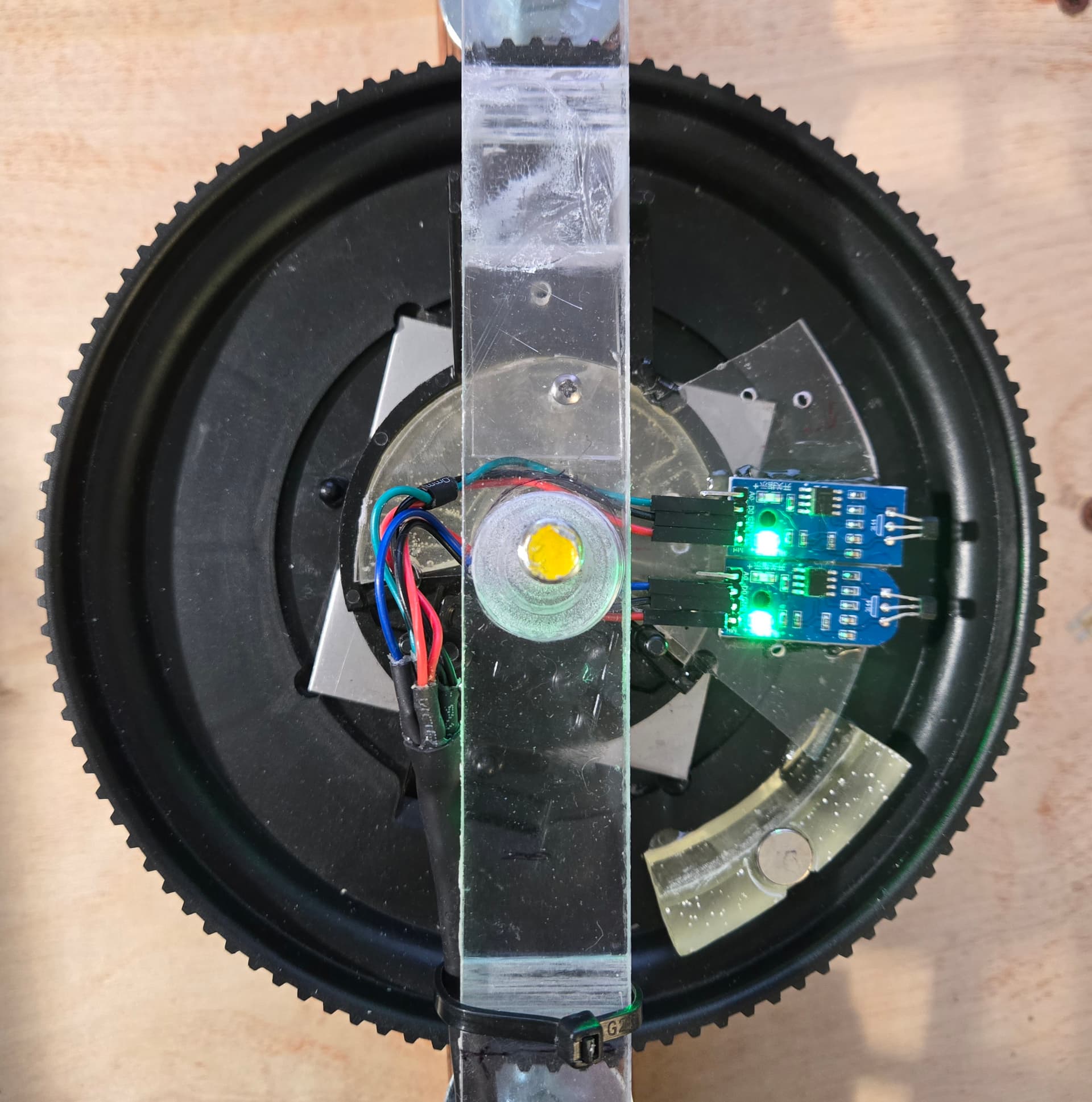
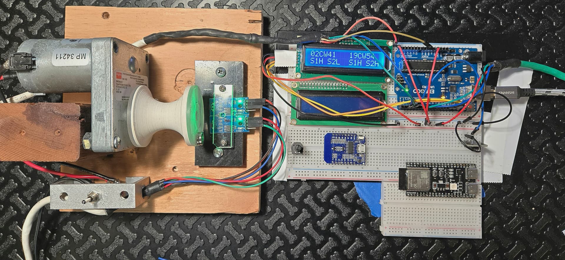
Rotor: I am currently using two prototypes for testing. One is just a small motor with a rotating pulley that has a neodymium disc magnate (9mm x 3mm) glued to the circular face. The magnets pass two Unnamed Hall Effect Sensor Modules that use A3141 chipset. The larger rotor is a life-sized rotor removed from a broken downrigger that I turn with a rechargeable hand drill. It has the same sensor modules.

Display: A 1602 I2C generic display that has no potentiometer.

Microprocessor: Arduino Uno Rev3

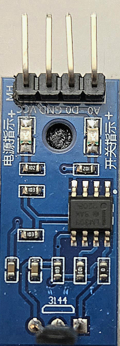
HALL EFFECT SENSORS: I am using cheap modules bought on Amazon. I don’t have data sheet but they incorporate the 3144E switch type sensor. The data sheet for this is attached. I also bought some KY-024 Linear Magnetic Hall Effect Sensor Modules which use the same sensor but incorporate a potentiometer which I thought might be useful if problems stemmed from strength of magnetic field. But I never used as connecting wires of sensors were bent up.

Wiring: The two sensors on the small rotor unit are attached by 6 wires.

  • The GND and VCC from all sensors are each combined and attached to the ground and 5 v pins of the Arduino.
  • The DO sensor wires from the small rotor are attached to pins 2 and 3 of the Arduino.
  • The DO sensor wires of the large rotor go to pins 6 and 7 of the Arduino.
  • A Reset push button to GND is connected to pin 4

Rotational Frequency: The small rotor turns at a fixed rate of about 60 rpm. The Large rotor rate is highly variable, as it is controlled by a heavy-duty cordless hand drill attached to the spindle from below. The real unit rotates from barely turning to a maximum of about 480 rpm. (It went from 0-100 rotations in about 13 seconds.)

POWER SUPPLY: The prototype is powered by the USB B cable. The rotors and microprocessors will be powered by two large 12 volt AGM batteries (60 + 80 amp hour capacity) or possibly by two 12 volt, LiFePO4, 105 amp hour batteries. I have not yet considered which way I will reduce voltage to 5v or 3.3v. The cell phone will be charged normally by a USB 3 cable from a 12 volt adapter. It can be on batteries if mobility is required.

ATTACHMENTS: I will attach the following documents.

  • Schematic of Bidirectional Rotor Counter
  • 3144 Hall Effect Sensor Data Sheet
  • KY-024 Data Sheet
  • Pictures the generic 3144 Sensor and the KY-024
  • Picture of Rotors and Setup

```cpp
//THIS IS REDO OF CopilotGitHub_Best_LCD_B4_OLED_4_42_V7_NOCOMMENTS

#include <Wire.h>
#include <LiquidCrystal_I2C.h>
#include <EEPROM.h>

#define I2C_ADDR 0x27
#define LCD_COLUMNS 16
#define LCD_ROWS 2

LiquidCrystal_I2C lcd(I2C_ADDR, LCD_COLUMNS, LCD_ROWS);

const int hallSensor1Pin1 = 2;
const int hallSensor2Pin1 = 3;
const int hallSensor1Pin2 = 6;
const int hallSensor2Pin2 = 7;
const int resetButtonPin = 4;

int lastStateSensor1_1 = LOW;
int lastStateSensor2_1 = LOW;
int currentStateSensor1_1 = LOW;
int currentStateSensor2_1 = LOW;

int lastStateSensor1_2 = LOW;
int lastStateSensor2_2 = LOW;
int currentStateSensor1_2 = LOW;
int currentStateSensor2_2 = LOW;

int netCount1 = 0;  // NET COUNT FOR ROTOR 1 (CW ROTATIONS - CCW ROTATIONS)
long absoluteRotations1 = 0;

int netCount2 = 0;
long absoluteRotations2 = 0;

int lastButtonState = HIGH;
int currentButtonState = HIGH;
unsigned long lastDebounceTime = 0;
unsigned long debounceDelay = 50;

bool rotationDetected1 = false;
bool rotationDetected2 = false;
String rotationDirection1 = "";
String rotationDirection2 = "";

void readSensors();
void detectRotation();
void handleButtonPress();
void updateDisplay();
String padZero(int num, int width);
void displayCount();
void saveCountToEEPROM();

void setup() {
  Serial.begin(9600);
  pinMode(hallSensor1Pin1, INPUT);  // SET hallSensor1Pin1 AS INPUT
  pinMode(hallSensor2Pin1, INPUT);  // SET hallSensor2Pin1 AS INPUT
  pinMode(hallSensor1Pin2, INPUT);  // SET hallSensor1Pin2 AS INPUT
  pinMode(hallSensor2Pin2, INPUT);  // SET hallSensor2Pin2 AS INPUT
  pinMode(resetButtonPin, INPUT_PULLUP);

  lcd.begin(LCD_COLUMNS, LCD_ROWS);
  lcd.backlight();
  lcd.setCursor(0, 0);
  lcd.print("Initializing...");
  delay(2000);
  lcd.clear();


  netCount1 = EEPROM.read(0) | (EEPROM.read(1) << 8);
  netCount2 = EEPROM.read(2) | (EEPROM.read(3) << 8);

  displayCount();
}

void loop() {
  readSensors();
  detectRotation();
  handleButtonPress();
  updateDisplay();
  delay(10);
}

void readSensors() {
  currentStateSensor1_1 = digitalRead(hallSensor1Pin1);
  currentStateSensor2_1 = digitalRead(hallSensor2Pin1);


  currentStateSensor1_2 = digitalRead(hallSensor1Pin2);
  currentStateSensor2_2 = digitalRead(hallSensor2Pin2);
}

void detectRotation() {

  if (currentStateSensor1_1 == HIGH && lastStateSensor1_1 == LOW && currentStateSensor2_1 == LOW) {
    rotationDirection1 = "CW";
    netCount1++;
    absoluteRotations1++;
    rotationDetected1 = true;
    saveCountToEEPROM();
  } else if (currentStateSensor2_1 == HIGH && lastStateSensor2_1 == LOW && currentStateSensor1_1 == LOW) {
    rotationDirection1 = "CCW";
    if (netCount1 > 0) {
      netCount1--;
      absoluteRotations1++;
      rotationDetected1 = true;
      saveCountToEEPROM();
    }
  }


  if (currentStateSensor1_2 == HIGH && lastStateSensor1_2 == LOW && currentStateSensor2_2 == LOW) {
    rotationDirection2 = "CW";
    netCount2++;
    absoluteRotations2++;
    rotationDetected2 = true;
    saveCountToEEPROM();
  } else if (currentStateSensor2_2 == HIGH && lastStateSensor2_2 == LOW && currentStateSensor1_2 == LOW) {
    rotationDirection2 = "CCW";
    if (netCount2 > 0) {
      netCount2--;
      absoluteRotations2++;
      rotationDetected2 = true;
      saveCountToEEPROM();
    }
  }

  lastStateSensor1_1 = currentStateSensor1_1;
  lastStateSensor2_1 = currentStateSensor2_1;
  lastStateSensor1_2 = currentStateSensor1_2;
  lastStateSensor2_2 = currentStateSensor2_2;
}

void handleButtonPress() {
  currentButtonState = digitalRead(resetButtonPin);

  if (currentButtonState == LOW && lastButtonState == HIGH && (millis() - lastDebounceTime) > debounceDelay) {
    netCount1 = 0;
    netCount2 = 0;
    absoluteRotations1 = 0;
    absoluteRotations2 = 0;
    Serial.println(" Reset to 0");
    lcd.clear();
    lcd.print(" Reset to 0");
    delay(1000);
    lcd.clear();
    saveCountToEEPROM();
    lastDebounceTime = millis();
  }
  lastButtonState = currentButtonState;
}

void updateDisplay() {
  if (rotationDetected1 || rotationDetected2) {
    displayCount();
    rotationDetected1 = false;
    rotationDetected2 = false;
  }
}

String padZero(int num, int width) {

  String str = String(num);
  while (str.length() < width) {
    str = "0" + str;
  }
  return str;
}

void displayCount() {

  String directionStr1 = rotationDirection1;
  String line1_1 = padZero(absoluteRotations1 % 100, 2) + directionStr1 + padZero(abs(netCount1) % 100, 2);
  String line2_1 = "S1" + String(currentStateSensor1_1 ? "H" : "L") + " S2" + String(currentStateSensor2_1 ? "H" : "L");

  String directionStr2 = rotationDirection2;
  String line1_2 = padZero(absoluteRotations2 % 100, 2) + directionStr2 + padZero(abs(netCount2) % 100, 2);
  String line2_2 = "S1" + String(currentStateSensor1_2 ? "H" : "L") + " S2" + String(currentStateSensor2_2 ? "H" : "L");

  lcd.clear();
  lcd.setCursor(0, 0);
  lcd.print(line1_1);
  lcd.setCursor(0, 1);
  lcd.print(line2_1);

  lcd.setCursor(9, 0);
  lcd.print(line1_2);
  lcd.setCursor(9, 1);
  lcd.print(line2_2);

  Serial.print("Rotor 1 - Absolute Rotations: ");
  Serial.print(absoluteRotations1);
  Serial.print(" Direction: ");
  Serial.print(rotationDirection1);
  Serial.print(" Net Count: ");
  Serial.print(netCount1);
  Serial.print(" S1: ");
  Serial.print(currentStateSensor1_1 ? "H" : "L");
  Serial.print(" S2: ");
  Serial.println(currentStateSensor2_1 ? "H" : "L");

  Serial.print("Rotor 2 - Absolute Rotations: ");
  Serial.print(absoluteRotations2);
  Serial.print(" Direction: ");
  Serial.print(rotationDirection2);
  Serial.print(" Net Count: ");
  Serial.print(netCount2);
  Serial.print(" S1: ");
  Serial.print(currentStateSensor1_2 ? "H" : "L");
  Serial.print(" S2: ");
  Serial.println(currentStateSensor2_2 ? "H" : "L");
}

void saveCountToEEPROM() {
  EEPROM.write(0, netCount1 & 0xFF);
  EEPROM.write(1, (netCount1 >> 8) & 0xFF);
  EEPROM.write(2, netCount2 & 0xFF);
  EEPROM.write(3, (netCount2 >> 8) & 0xFF);
}


3141 Hall Effect Sensor Data sheet.pdf (141.1 KB)
KY-024 Data Sheet.pdf (861.7 KB)


Since it looks like the sketch wasn't too long as I misunderstood what I was counting, I am including the sketch I was actually using as I had all the elements commented in CAPs so I could readily find and study individual elements.


```cpp
/*THIS IS REDO OF "CopilotGitHub_Best_LCD_B4_tried_OLED_4_42_V7_0112025"
It took the sketch and added 2nd rotor input and fixed th rising + count after reaching 0

Current resource demand:
Sketch uses 8872 bytes (27%) of program storage space. Maximum is 32256 bytes.
Global variables use 603 bytes (29%) of dynamic memory, leaving 1445 bytes for local variables. Maximum is 2048 bytes.

Change Total Count to Net Count

Add all Cap Commentary for each element of code
*/


#include <Wire.h>               // INCLUDE THE WIRE LIBRARY FOR I2C COMMUNICATION
#include <LiquidCrystal_I2C.h>  // INCLUDE THE LIQUIDCRYSTAL_I2C LIBRARY FOR LCD CONTROL
#include <EEPROM.h>             // INCLUDE THE EEPROM LIBRARY FOR STORING DATA IN NON-VOLATILE MEMORY

// DEFINE THE LCD ADDRESS AND DIMENSIONS
#define I2C_ADDR 0x27   // THE I2C ADDRESS OF THE LCD (CHANGE IF NECESSARY)
#define LCD_COLUMNS 16  // NUMBER OF COLUMNS ON THE LCD
#define LCD_ROWS 2      // NUMBER OF ROWS ON THE LCD

// CREATE AN OBJECT FOR THE LCD WITH THE SPECIFIED PARAMETERS
LiquidCrystal_I2C lcd(I2C_ADDR, LCD_COLUMNS, LCD_ROWS);

const int hallSensor1Pin1 = 2;  // ROTOR 1 HALL SENSOR 1 CONNECTED TO DIGITAL PIN 2
const int hallSensor2Pin1 = 3;  // ROTOR 1 HALL SENSOR 2 CONNECTED TO DIGITAL PIN 3
const int hallSensor1Pin2 = 6;  // ROTOR 2 HALL SENSOR 1 CONNECTED TO DIGITAL PIN 6
const int hallSensor2Pin2 = 7;  // ROTOR 2 HALL SENSOR 2 CONNECTED TO DIGITAL PIN 7
const int resetButtonPin = 4;   // RESET BUTTON CONNECTED TO DIGITAL PIN 4

// VARIABLES TO STORE THE STATES OF THE SENSORS FOR ROTOR 1
int lastStateSensor1_1 = LOW;
int lastStateSensor2_1 = LOW;
int currentStateSensor1_1 = LOW;
int currentStateSensor2_1 = LOW;

// VARIABLES TO STORE THE STATES OF THE SENSORS FOR ROTOR 2
int lastStateSensor1_2 = LOW;
int lastStateSensor2_2 = LOW;
int currentStateSensor1_2 = LOW;
int currentStateSensor2_2 = LOW;

// VARIABLES TO STORE THE COUNTS AND ROTATIONS FOR ROTOR 1
int netCount1 = 0;            // NET COUNT FOR ROTOR 1 (CW ROTATIONS - CCW ROTATIONS)
long absoluteRotations1 = 0;  // ABSOLUTE NUMBER OF ROTATIONS MADE IN BOTH DIRECTIONS FOR ROTOR 1

// VARIABLES TO STORE THE COUNTS AND ROTATIONS FOR ROTOR 2
int netCount2 = 0;            // NET COUNT FOR ROTOR 2 (CW ROTATIONS - CCW ROTATIONS)
long absoluteRotations2 = 0;  // ABSOLUTE NUMBER OF ROTATIONS MADE IN BOTH DIRECTIONS FOR ROTOR 2

// VARIABLES TO STORE THE BUTTON STATES
int lastButtonState = HIGH;  // INITIALIZED TO HIGH BECAUSE OF PULL-UP RESISTOR
int currentButtonState = HIGH;
unsigned long lastDebounceTime = 0;
unsigned long debounceDelay = 50;  // DEBOUNCE DELAY TO AVOID FALSE TRIGGERS

// VARIABLES TO DETECT ROTATION AND DIRECTION
bool rotationDetected1 = false;
bool rotationDetected2 = false;
String rotationDirection1 = "";
String rotationDirection2 = "";

// FUNCTION DECLARATIONS
void readSensors();
void detectRotation();
void handleButtonPress();
void updateDisplay();
String padZero(int num, int width);
void displayCount();
void saveCountToEEPROM();

void setup() {
  Serial.begin(9600);                     // START SERIAL COMMUNICATION AT 9600 BAUD RATE
  pinMode(hallSensor1Pin1, INPUT);        // SET hallSensor1Pin1 AS INPUT
  pinMode(hallSensor2Pin1, INPUT);        // SET hallSensor2Pin1 AS INPUT
  pinMode(hallSensor1Pin2, INPUT);        // SET hallSensor1Pin2 AS INPUT
  pinMode(hallSensor2Pin2, INPUT);        // SET hallSensor2Pin2 AS INPUT
  pinMode(resetButtonPin, INPUT_PULLUP);  // SET resetButtonPin AS INPUT WITH PULL-UP RESISTOR

  lcd.begin(LCD_COLUMNS, LCD_ROWS);  // INITIALIZE THE LCD WITH THE SPECIFIED COLUMNS AND ROWS
  lcd.backlight();                   // TURN ON THE BACKLIGHT
  lcd.setCursor(0, 0);               // SET CURSOR TO THE FIRST COLUMN, FIRST ROW
  lcd.print("Initializing...");      // DISPLAY A WELCOME MESSAGE
  delay(2000);                       // WAIT FOR 2 SECONDS
  lcd.clear();                       // CLEAR THE LCD

  // LOAD THE LAST COUNT FROM EEPROM
  netCount1 = EEPROM.read(0) | (EEPROM.read(1) << 8);
  netCount2 = EEPROM.read(2) | (EEPROM.read(3) << 8);

  // DISPLAY THE LAST COUNT ON THE LCD
  displayCount();
}

void loop() {
  readSensors();        // READ THE STATES OF THE SENSORS
  detectRotation();     // DETECT THE DIRECTION OF ROTATION AND UPDATE COUNTS
  handleButtonPress();  // HANDLE THE RESET BUTTON PRESS
  updateDisplay();      // UPDATE THE LCD DISPLAY
  delay(10);            // SMALL DELAY TO STABILIZE SENSOR STATES
}

void readSensors() {
  // READ THE CURRENT STATES OF THE SENSORS FOR ROTOR 1
  currentStateSensor1_1 = digitalRead(hallSensor1Pin1);
  currentStateSensor2_1 = digitalRead(hallSensor2Pin1);

  // READ THE CURRENT STATES OF THE SENSORS FOR ROTOR 2
  currentStateSensor1_2 = digitalRead(hallSensor1Pin2);
  currentStateSensor2_2 = digitalRead(hallSensor2Pin2);
}

void detectRotation() {
  // FOR ROTOR 1
  if (currentStateSensor1_1 == HIGH && lastStateSensor1_1 == LOW && currentStateSensor2_1 == LOW) {
    rotationDirection1 = "CW";  // SET DIRECTION TO CLOCKWISE
    netCount1++;                // INCREMENT NET COUNT
    absoluteRotations1++;       // INCREMENT ABSOLUTE ROTATIONS
    rotationDetected1 = true;   // SET ROTATION DETECTED FLAG
    saveCountToEEPROM();        // SAVE THE UPDATED COUNT TO EEPROM
  } else if (currentStateSensor2_1 == HIGH && lastStateSensor2_1 == LOW && currentStateSensor1_1 == LOW) {
    rotationDirection1 = "CCW";  // SET DIRECTION TO COUNTER-CLOCKWISE
    if (netCount1 > 0) {         // ENSURE THE COUNT DOES NOT GO BELOW 0
      netCount1--;               // DECREMENT NET COUNT
      absoluteRotations1++;      // INCREMENT ABSOLUTE ROTATIONS
      rotationDetected1 = true;  // SET ROTATION DETECTED FLAG
      saveCountToEEPROM();       // SAVE THE UPDATED COUNT TO EEPROM
    }
  }

  // FOR ROTOR 2
  if (currentStateSensor1_2 == HIGH && lastStateSensor1_2 == LOW && currentStateSensor2_2 == LOW) {
    rotationDirection2 = "CW";  // SET DIRECTION TO CLOCKWISE
    netCount2++;                // INCREMENT NET COUNT
    absoluteRotations2++;       // INCREMENT ABSOLUTE ROTATIONS
    rotationDetected2 = true;   // SET ROTATION DETECTED FLAG
    saveCountToEEPROM();        // SAVE THE UPDATED COUNT TO EEPROM
  } else if (currentStateSensor2_2 == HIGH && lastStateSensor2_2 == LOW && currentStateSensor1_2 == LOW) {
    rotationDirection2 = "CCW";  // SET DIRECTION TO COUNTER-CLOCKWISE
    if (netCount2 > 0) {         // ENSURE THE COUNT DOES NOT GO BELOW 0
      netCount2--;               // DECREMENT NET COUNT
      absoluteRotations2++;      // INCREMENT ABSOLUTE ROTATIONS
      rotationDetected2 = true;  // SET ROTATION DETECTED FLAG
      saveCountToEEPROM();       // SAVE THE UPDATED COUNT TO EEPROM
    }
  }

  // UPDATE LAST STATE VARIABLES TO CURRENT STATES
  lastStateSensor1_1 = currentStateSensor1_1;
  lastStateSensor2_1 = currentStateSensor2_1;
  lastStateSensor1_2 = currentStateSensor1_2;
  lastStateSensor2_2 = currentStateSensor2_2;
}

void handleButtonPress() {
  currentButtonState = digitalRead(resetButtonPin);  // READ THE CURRENT STATE OF THE RESET BUTTON

  if (currentButtonState == LOW && lastButtonState == HIGH && (millis() - lastDebounceTime) > debounceDelay) {
    // IF BUTTON IS PRESSED, RESET THE COUNTS AND ROTATIONS
    netCount1 = 0;
    netCount2 = 0;
    absoluteRotations1 = 0;
    absoluteRotations2 = 0;
    Serial.println(" Reset to 0");
    lcd.clear();
    lcd.print(" Reset to 0");
    delay(1000);
    lcd.clear();
    saveCountToEEPROM();          // SAVE THE RESET COUNT TO EEPROM
    lastDebounceTime = millis();  // UPDATE THE DEBOUNCE TIME
  }
  lastButtonState = currentButtonState;  // UPDATE LAST BUTTON STATE
}

void updateDisplay() {
  if (rotationDetected1 || rotationDetected2) {
    displayCount();  // IF A ROTATION IS DETECTED, UPDATE THE DISPLAY
    rotationDetected1 = false;
    rotationDetected2 = false;
  }
}

String padZero(int num, int width) {
  // FUNCTION TO PAD NUMBERS WITH LEADING ZEROS
  String str = String(num);
  while (str.length() < width) {
    str = "0" + str;
  }
  return str;
}

void displayCount() {
  // PREPARE THE STRINGS WITH THE REQUIRED FORMAT FOR ROTOR 1
  String directionStr1 = rotationDirection1;
  String line1_1 = padZero(absoluteRotations1 % 100, 2) + directionStr1 + padZero(abs(netCount1) % 100, 2);
  String line2_1 = "S1" + String(currentStateSensor1_1 ? "H" : "L") + " S2" + String(currentStateSensor2_1 ? "H" : "L");

  // PREPARE THE STRINGS WITH THE REQUIRED FORMAT FOR ROTOR 2
  String directionStr2 = rotationDirection2;
  String line1_2 = padZero(absoluteRotations2 % 100, 2) + directionStr2 + padZero(abs(netCount2) % 100, 2);
  String line2_2 = "S1" + String(currentStateSensor1_2 ? "H" : "L") + " S2" + String(currentStateSensor2_2 ? "H" : "L");

  // CLEAR THE LCD AND PRINT THE LINES FOR ROTOR 1
  lcd.clear();
  lcd.setCursor(0, 0);  // SET CURSOR FOR line1_1 TO THE BEGINNING OF THE FIRST ROW
  lcd.print(line1_1);
  lcd.setCursor(0, 1);  // SET CURSOR FOR line2_1 TO THE BEGINNING OF THE SECOND ROW
  lcd.print(line2_1);

  // PRINT THE COUNTS FOR ROTOR 2 STARTING AT COLUMN 9
  lcd.setCursor(9, 0);  // SET CURSOR FOR line1_2 TO THE 9TH COLUMN OF THE FIRST ROW
  lcd.print(line1_2);
  lcd.setCursor(9, 1);  // SET CURSOR FOR line2_2 TO THE 9TH COLUMN OF THE SECOND ROW
  lcd.print(line2_2);

  // PRINT TO SERIAL MONITOR FOR DEBUGGING
  Serial.print("Rotor 1 - Absolute Rotations: ");
  Serial.print(absoluteRotations1);
  Serial.print(" Direction: ");
  Serial.print(rotationDirection1);
  Serial.print(" Net Count: ");
  Serial.print(netCount1);
  Serial.print(" S1: ");
  Serial.print(currentStateSensor1_1 ? "H" : "L");
  Serial.print(" S2: ");
  Serial.println(currentStateSensor2_1 ? "H" : "L");

  Serial.print("Rotor 2 - Absolute Rotations: ");
  Serial.print(absoluteRotations2);
  Serial.print(" Direction: ");
  Serial.print(rotationDirection2);
  Serial.print(" Net Count: ");
  Serial.print(netCount2);
  Serial.print(" S1: ");
  Serial.print(currentStateSensor1_2 ? "H" : "L");
  Serial.print(" S2: ");
  Serial.println(currentStateSensor2_2 ? "H" : "L");
}

void saveCountToEEPROM() {
  // SAVE THE COUNTS TO EEPROM
  EEPROM.write(0, netCount1 & 0xFF);         // WRITE THE LOWER BYTE OF netCount1
  EEPROM.write(1, (netCount1 >> 8) & 0xFF);  // WRITE THE UPPER BYTE OF netCount1
  EEPROM.write(2, netCount2 & 0xFF);         // WRITE THE LOWER BYTE OF netCount2
  EEPROM.write(3, (netCount2 >> 8) & 0xFF);  // WRITE THE UPPER BYTE OF netCount2
}

Hope I can at least start with this. Sorry I used a sketch drawing I had already made to show someone. I hope its not so terrible that it won't suffice.

Thanks

this must be frustrating for you. a 1400+ word response and two 250+ line pieces of code

but would you mind providing a more succint description of what you're trying to do ... rather than how you think to do it.

... looking over the code, what doesn't it do that you want?

You seem to write to the EEPROM very very often.
Are you aware of that the EEPROM will be worn out after 100 000 writecycles?

If you want to want to do 10^12 writings use a FRAM-module

Displaying
10CCW11____02CCW21
S1L S2H______S3H S4L

is not a selfpurpose
I would like to know what the finale purpose of displaying such numbers is

i needed to change the partition to allocate more memory when i added Bluetooth to an esp32 application.

how frequent? how fast can your eye see a change? would once a second be adequate

i've been working on an esp32 program that transmits a string with 3 acceleration and 3 gyro
6-digit values over broadcast UDP msg and am using a Java program to display them on a laptop. A string is sent every 100 msec.

wifi doesn't seem to need as much memory as Bluetooth

An Arduino would need a separate Bluetooth module and i don't know if a Mega has enough memory

i'm not familiar with phone apps