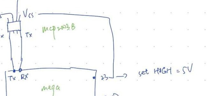
I'm trying to control a proportional valve using the LIN protocol. I connected the valve and the Arduino mega board using a mc2003b chip. Here's my code to send the signal, but it actually doesn't work.
The frame structure should be:
Byte 0: NAD
Byte 1: reserved
Byte 2: position state and speed
Byte 3-4: set requid position
5-7: reserved
I'm new to a LIN protocol programing, but i think all the structures are correct in my code, so why does it still not working?
#include "Arduino.h"
#include "lin.h"
#include <HardwareSerial.h>

Lin lin(Serial2, 17); // create LIN interface using UART2, RXD = Pin 16, TXD = Pin 17

void setup(void)
{
  Serial.begin(19200); // initialize serial communication with PC for debug

  pinMode(32, OUTPUT); // set pin 32 as output for power control of valve
  digitalWrite(32, HIGH); // set pin 32 high to power on valve

  lin.begin(19200);
}


void loop(void)
{
  uint8_t NAD = 0x3C;
  uint8_t buf[8]= {0};
  uint8_t bitmask1 = 0b01000001;
  uint8_t bitmask2 = 0b00010001;
  uint8_t bitmask3 = 0b10010100;
  uint8_t nBytes = 8;
  uint8_t proto = 2;
  uint8_t subsystem_id = 0x47; // subsystem ID = 0x747 >> 5 = 0x47
  uint8_t data1 = 65;
  uint8_t Position1 = 5;
  uint8_t Position2 = 220;
  uint8_t Failsafe = 0;
  uint8_t padding_byte = 0xFF;

  // Build the message
  buf[0] = NAD;
  buf[1] = 0xFF;
  buf[2] = data1;
  buf[3] = position1;
  buf[4] = position2;
  buf[5] = 0xFF;
  buf[6] = 0xFF;
  buf[7] = 0x00;


  lin.send(0x31, buf, sizeof(buf), 2); // send LIN message to valve with address 0x31, using NAD 0x3C and subsystem ID 0x747

  delay(500);
}
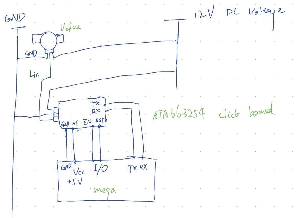
Oh, i got the Vss abd Vbb mixed up in the diagram. I connected the Vbb to the I/O pin to make the pin serve as the supply voltage. But now i think i need to connect that with a 12V power supply according to the datasheet.
and the schematic of it. So this time i'm preetty positive that i made it right.
Then this is the libraries that required to use the click board.
And this is my code right now.
#include "mikrosdk_v2-master.h"
#include "ata663254.h"
#include "Arduino.h"
#include "lin.h"
#include <HardwareSerial.h>

Lin lin(Serial2, 17); // create LIN interface using UART2, RXD = Pin 16, TXD = Pin 17

// ------------------------------------------------------------------ VARIABLES

#define DEMO_APP_RECEIVER
// #define DEMO_APP_TRANSMITTER

static ata663254_t ata663254;
static log_t logger;

static char rec_buf[ 50 ] = { 0 };

uint8_t NAD = 0x3C;
uint8_t buf[8]= {0};
uint8_t bitmask1 = 0b01000001;
uint8_t bitmask2 = 0b00010001;
uint8_t bitmask3 = 0b10010100;
uint8_t nBytes = 8;
uint8_t proto = 2;
uint8_t subsystem_id = 0x47; // subsystem ID = 0x747 >> 5 = 0x47
uint8_t data1 = 65;
uint8_t Position1 = 5;
uint8_t Position2 = 220;
uint8_t Failsafe = 0;
uint8_t padding_byte = 0xFF;

// Build the message
buf[0] = NAD;
buf[1] = 0xFF;
buf[2] = data1;
buf[3] = position1;
buf[4] = position2;
buf[5] = 0xFF;
buf[6] = 0xFF;
buf[7] = 0x00;

// ------------------------------------------------------ APPLICATION FUNCTIONS

void application_init ( void )
{
    log_cfg_t log_cfg;
    ata663254_cfg_t cfg;

    /**
     * Logger initialization.
     * Default baud rate: 115200
     * Default log level: LOG_LEVEL_DEBUG
     * @note If USB_UART_RX and USB_UART_TX
     * are defined as HAL_PIN_NC, you will
     * need to define them manually for log to work.
     * See @b LOG_MAP_USB_UART macro definition for detailed explanation.
     */
    LOG_MAP_USB_UART( log_cfg );
    log_init( &logger, &log_cfg );
    log_info( &logger, "---- Application Init ----" );

    //  Click initialization.

    ata663254_cfg_setup( &cfg );
    ATA663254_MAP_MIKROBUS( cfg, MIKROBUS_1 );
    ata663254_init( &ata663254, &cfg );

    ata663254_enable( &ata663254, 1 );
    Delay_ms( 1000 );
}

void application_task ( void )
{
#ifdef DEMO_APP_RECEIVER

    // RECEIVER - UART polling

    int32_t len = ata663254_generic_read( &ata663254, rec_buf, 50 );
    if ( len > 0 )
    {
        log_printf( &logger, "Received data: " );
        for ( int32_t cnt = 0; cnt < len; cnt++  )
        {
            log_printf( &logger, "%c", rec_buf[ cnt ] );
        }
        memset( rec_buf, 0 , 50 );
    }
    Delay_ms( 100 );
#endif
#ifdef DEMO_APP_TRANSMITTER

    // TRANSMITER - TX each 2 sec

    ata663254_generic_write( &ata663254, buf, 8 );
    log_info( &logger, "--- Data sent ---" );

    Delay_ms( 2000 );
#endif
}

void setup() {
  // put your setup code here, to run once:
  Serial.begin(19200); // initialize serial communication with PC for debug

  pinMode(32, OUTPUT); // set pin 32 as output for power control of valve
  digitalWrite(32, HIGH); // set pin 32 high to power on valve

  lin.begin(19200);
}

void loop() {
  // put your main code here, to run repeatedly:
  lin.send(0x31, buf, sizeof(buf), 2); // send LIN message to valve with address 0x31, using NAD 0x3C and subsystem ID 0x747

  delay(500);
  application_init( );
  application_task( );

}
Now the problem is: 1. if i use this new library to send the message, should i add the code manually to send first the sync break byte and message ID byte then the buf? Or i can still use the lin library to send my message?
2. It's always 'No such file ' about the the library mikrosdk_v2. I have post another topic about this and have so far no answer. this is the link.