Control cabinet with 12 electric locks

Good morning, it is a pleasure for me to be part of this community.

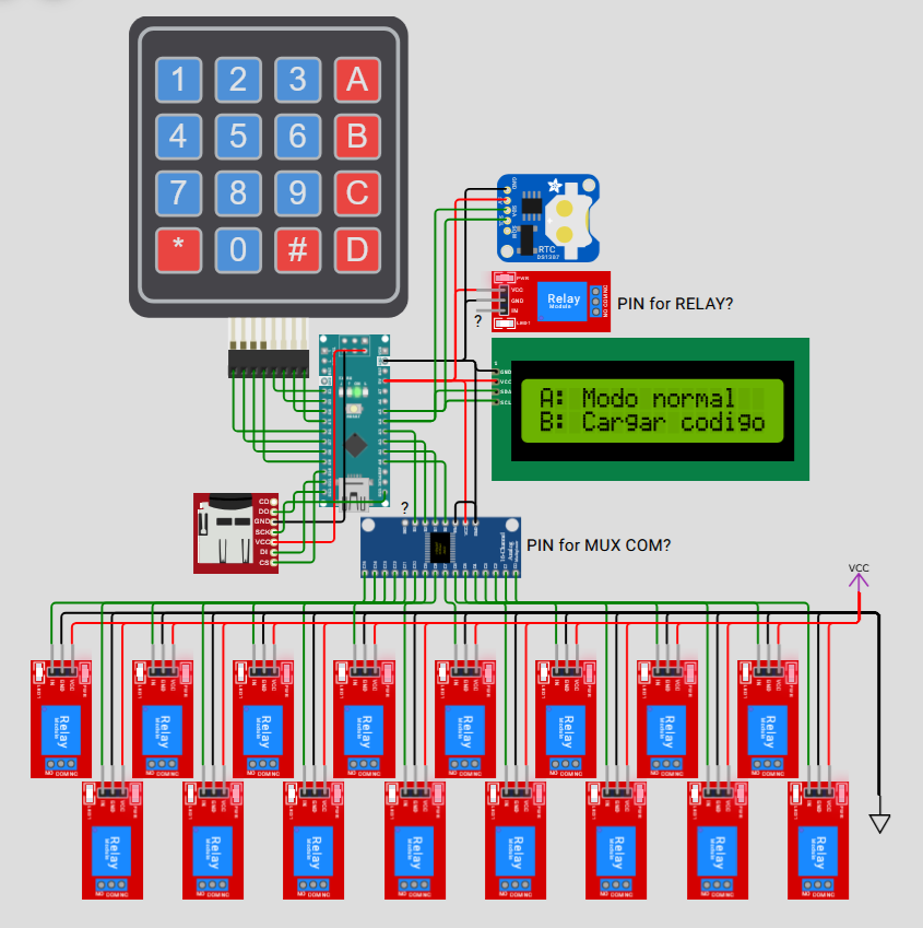
I am developing a cabinet with 12 electric locks, with a LCD display with I2C, whose access is done through a 4x4 keypad and a 4 digit user code assigned to a person. Then you are asked to choose the door you want to open from 1 to 12 and the selected relay is activated.

All this is registered in a microSD, thanks to a SD module and a DS3231 clock.

I have a problem that I can't solve. I bought a 16 relay module from aliexpress. When I start the program, let me enter the code, validate it and choose the door, at this point, the multiplexer cd74hc4067 does not activate the relay I select, the relay board does not respond, I do not know if it is a connection fault or what happens. I control all this with an arduino nano. The relay board has the 16 inputs, 2 VCC and 2 GND and two more connectors, DC+ and DC-. I leave the code in case I am making a mistake. Even if I measure the voltage between GND and the SIG pin of the multiplexer, I get 4,7V. However, if I test relay board and multiplexer separately, it works correctly.

Thank you in advance for your attention.

#include <Keypad.h>
#include <EEPROM.h>
#include <LiquidCrystal_I2C.h>
#include <RTClib.h>
#include <SPI.h>
#include <SD.h>

// === CONFIGURACIÓN DEL TECLADO ===
const byte ROWS = 4, COLS = 4;
char keys[ROWS][COLS] = {
  {'1','2','3','A'},
  {'4','5','6','B'},
  {'7','8','9','C'},
  {'*','0','#','D'}
};
byte rowPins[ROWS] = {6, 7, 8, 9};
byte colPins[COLS] = {2, 3, 4, 5};
Keypad keypad = Keypad(makeKeymap(keys), rowPins, colPins, ROWS, COLS);

// === CONFIGURACIÓN DE LA LCD ===
LiquidCrystal_I2C lcd(0x27, 16, 2);

// === RTC ===
RTC_DS3231 rtc;

// === MÓDULO SD ===
const int SD_CS = 10;

// === PINES ===
const int relePin = 8;  // Pin de control del relé

// === CONSTANTES ===
const int NUM_CODIGOS = 25;
const int DIGITOS = 4;
const int NUM_PUERTAS = 12;
bool modoCarga = false;

// === FUNCIONES ===
void activarPuerta(byte puerta) {
  // Activación del relé
  digitalWrite(relePin, HIGH);  // El relé se activa (pin en HIGH)
  delay(10000);  // Mantener el relé activado durante 10 segundos
  digitalWrite(relePin, LOW);   // El relé se desactiva (pin en LOW)
}

bool validarCodigo(String codigo) {
  for (int i = 0; i < NUM_CODIGOS; i++) {
    String guardado = "";
    for (int j = 0; j < DIGITOS; j++) {
      guardado += String(EEPROM.read(i * DIGITOS + j));
    }
    if (codigo == guardado) return true;
  }
  return false;
}

void registrarAcceso(String codigo, byte puerta) {
  DateTime now = rtc.now();
  File log = SD.open("accesos.txt", FILE_WRITE);
  if (log) {
    log.print(now.timestamp());
    log.print(", Codigo: ");
    log.print(codigo);
    log.print(", Puerta: ");
    log.println(puerta);
    log.close();
  }
}

// === SETUP ===
void setup() {
  lcd.init();
  lcd.backlight();
  lcd.clear();
  pinMode(relePin, OUTPUT);  // Configura el pin de control como salida
  digitalWrite(relePin, LOW);  // Inicialmente el relé está apagado

  if (!rtc.begin()) {
    lcd.print("Error RTC");
    while (1);
  }

  if (!SD.begin(SD_CS)) {
    lcd.print("Error SD");
    while (1);
  }

  lcd.setCursor(0, 0);
  lcd.print("A: Modo normal");
  lcd.setCursor(0, 1);
  lcd.print("B: Cargar codigos");

  while (true) {
    char key = keypad.getKey();
    if (key == 'A') break;
    if (key == 'B') {
      modoCarga = true;
      break;
    }
  }

  if (modoCarga) {
    lcd.clear();
    lcd.print("Cargar codigos");
    delay(1000);
    for (int i = 0; i < NUM_CODIGOS; i++) {
      lcd.clear();
      lcd.print("Codigo #");
      lcd.print(i + 1);
      lcd.setCursor(0, 1);
      String codigo = "";
      while (codigo.length() < DIGITOS) {
        char key = keypad.getKey();
        if (key && isDigit(key)) {
          codigo += key;
          lcd.print("*");
        }
      }
      for (int j = 0; j < DIGITOS; j++) {
        EEPROM.write(i * DIGITOS + j, codigo[j] - '0');
      }
      delay(500);
    }
    lcd.clear();
    lcd.print("Carga completa");
    while (1);
  }

  lcd.clear();
  lcd.print("Sistema listo");
  delay(1000);
}

// === LOOP PRINCIPAL ===
void loop() {
  lcd.clear();
  lcd.print("Codigo:");
  lcd.setCursor(0, 1);
  String codigo = "";
  while (codigo.length() < DIGITOS) {
    char key = keypad.getKey();
    if (key && isDigit(key)) {
      codigo += key;
      lcd.print("*");
    }
  }

  if (!validarCodigo(codigo)) {
    lcd.clear();
    lcd.print("Codigo invalido");
    delay(1500);
    return;
  }

  lcd.clear();
  lcd.print("Puerta (1-12):");
  String puertaStr = "";
  while (puertaStr.length() < 1) {
    char key = keypad.getKey();
    if (key && isDigit(key)) {
      puertaStr += key;
      lcd.print(key);
    }
  }

  byte puerta = puertaStr.toInt();
  if (puerta < 1 || puerta > NUM_PUERTAS) {
    lcd.clear();
    lcd.print("Puerta invalida");
    delay(1500);
    return;
  }

  // Mostrar "ACCESO OK" y activar el relé durante 10 segundos
  lcd.clear();
  lcd.print("Acceso OK");
  activarPuerta(puerta - 1);  // Activa el relé para abrir la puerta
  registrarAcceso(codigo, puerta);

  lcd.clear();
  lcd.print("Acceso completado");
  delay(2000);  // Mostrar el mensaje de acceso completado
}

Do not start multiple topics with the same subject. Chose one, remove the other.

Hi, @sr_tijera

Have you got some simple code that proves you have control of the multiplexer?

If you wrote your code in stages, you should have this simple code.

Can you please post a copy of your circuit, a picture of a hand drawn circuit in jpg, png?
Hand drawn and photographed is perfectly acceptable.
Please include ALL hardware, power supplies, component names and pin labels.

Thanks... Tom.... :smiley: :+1: :coffee: :australia:

Connection Diagram:

  1. Connection of the Matrix Keyboard (4x4):

R1 → Pin D6 of the Arduino Nano

R2 → Pin D7 of the Arduino Nano

R3 → Pin D8 of the Arduino Nano

R4 → Pin D9 of the Arduino Nano

C1 → Pin D2 of the Arduino Nano

C2 → Pin D3 of the Arduino Nano

C3 → Pin D4 of the Arduino Nano

C4 → Pin D5 of the Arduino Nano

  1. Connection of the LCD Display (I2C):

SDA → A4 of the Arduino Nano

SCL → A5 of the Arduino Nano

VCC → 5V of the Arduino Nano

GND → GND of the Arduino Nano

  1. Connection of the DS3231 RTC Module:

SDA → A4 of the Arduino Nano

SCL → A5 of the Arduino Nano

VDC → 5V of the Arduino Nano

GND → GND of the Arduino Nano

  1. Connection of the SD Module:

MISO → Pin D12 of the Arduino Nano

MOSI → Pin D11 of the Arduino Nano

SCK → Pin D13 of the Arduino Nano

CS → Pin D10 of the Arduino Nano

VCC → 5V of the Arduino Nano

GND → GND of the Arduino Nano

  1. Multiplexer connection (for 12 gates):

S0 → Pin A0 of the Arduino Nano

S1 → Pin A1 of the Arduino Nano

S2 → Pin A2 of the Arduino Nano

S3 → Pin A3 of the Arduino Nano

COM_PIN (Control) → Pin D2 (you can choose any control pin to open the relay, but make sure it does not interfere with other components)

  1. Relay Board Connection:

IN1 - IN16 (for 16 relays) → Connect them to the Arduino control pins (you can use 16 available GPIO pins like D0, D1, D3... D12).

VCC → 5V from the Arduino Nano

GND → GND from the Arduino Nano

Hi,
Sorry, a picture/schematic is worth a thousand words.

Can you please post a copy of your circuit, a picture of a hand drawn circuit in jpg, png?
Hand drawn and photographed is perfectly acceptable.
Please include ALL hardware, power supplies, component names and pin labels.

Have you got a simple test code?

Tom.... :smiley: :+1: :coffee: :australia:

You copy/pasted a few sketches, poorly ([edit] but it still compiles and "works" what's the combo stored in EEPROM?). Here, you are using pins for multiple devices. And you never declare pins for the mux. Send it back to chatGPT or dump it and start with controlling one device and add to it.

Did you delete your other topic with the same subject?

diagram.json for wokwi.com
{
  "version": 1,
  "author": "Anonymous maker",
  "editor": "wokwi",
  "parts": [
    {
      "type": "wokwi-arduino-nano",
      "id": "nano",
      "top": 26,
      "left": -85.1,
      "rotate": 270,
      "attrs": {}
    },
    {
      "type": "board-cd74hc4067",
      "id": "mux1",
      "top": 100.01,
      "left": 50.75,
      "rotate": 270,
      "attrs": {}
    },
    {
      "type": "wokwi-membrane-keypad",
      "id": "keypad1",
      "top": -328.4,
      "left": -215.2,
      "attrs": {}
    },
    {
      "type": "wokwi-lcd1602",
      "id": "lcd1",
      "top": -22.4,
      "left": 130.4,
      "attrs": { "pins": "i2c" }
    },
    { "type": "wokwi-relay-module", "id": "relay1", "top": -86.2, "left": 115.2, "attrs": {} },
    { "type": "wokwi-ds1307", "id": "rtc1", "top": -178.2, "left": 134.5, "attrs": {} },
    { "type": "wokwi-microsd-card", "id": "sd1", "top": 125.03, "left": -153.53, "attrs": {} },
    {
      "type": "wokwi-text",
      "id": "text1",
      "top": -67.2,
      "left": 249.6,
      "attrs": { "text": "PIN for RELAY?" }
    },
    {
      "type": "wokwi-text",
      "id": "text2",
      "top": 163.2,
      "left": 163.2,
      "attrs": { "text": "PIN for MUX COM?" }
    },
    {
      "type": "wokwi-relay-module",
      "id": "relay6",
      "top": 303.8,
      "left": -150.8,
      "rotate": 90,
      "attrs": {}
    },
    {
      "type": "wokwi-relay-module",
      "id": "relay7",
      "top": 419,
      "left": -102.8,
      "rotate": 90,
      "attrs": {}
    },
    {
      "type": "wokwi-relay-module",
      "id": "relay8",
      "top": 303.8,
      "left": -54.8,
      "rotate": 90,
      "attrs": {}
    },
    {
      "type": "wokwi-relay-module",
      "id": "relay9",
      "top": 419,
      "left": -6.8,
      "rotate": 90,
      "attrs": {}
    },
    {
      "type": "wokwi-relay-module",
      "id": "relay10",
      "top": 303.8,
      "left": 41.2,
      "rotate": 90,
      "attrs": {}
    },
    {
      "type": "wokwi-relay-module",
      "id": "relay11",
      "top": 419,
      "left": 89.2,
      "rotate": 90,
      "attrs": {}
    },
    {
      "type": "wokwi-relay-module",
      "id": "relay12",
      "top": 303.8,
      "left": 137.2,
      "rotate": 90,
      "attrs": {}
    },
    {
      "type": "wokwi-relay-module",
      "id": "relay13",
      "top": 419,
      "left": 185.2,
      "rotate": 90,
      "attrs": {}
    },
    {
      "type": "wokwi-relay-module",
      "id": "relay14",
      "top": 303.8,
      "left": 233.2,
      "rotate": 90,
      "attrs": {}
    },
    {
      "type": "wokwi-relay-module",
      "id": "relay15",
      "top": 419,
      "left": 281.2,
      "rotate": 90,
      "attrs": {}
    },
    {
      "type": "wokwi-relay-module",
      "id": "relay16",
      "top": 303.8,
      "left": 329.2,
      "rotate": 90,
      "attrs": {}
    },
    {
      "type": "wokwi-relay-module",
      "id": "relay17",
      "top": 419,
      "left": 377.2,
      "rotate": 90,
      "attrs": {}
    },
    { "type": "wokwi-vcc", "id": "vcc1", "top": 192.76, "left": 470.4, "attrs": {} },
    { "type": "wokwi-gnd", "id": "gnd1", "top": 412.8, "left": 489, "attrs": {} },
    {
      "type": "wokwi-relay-module",
      "id": "relay2",
      "top": 303.8,
      "left": -342.8,
      "rotate": 90,
      "attrs": {}
    },
    {
      "type": "wokwi-relay-module",
      "id": "relay3",
      "top": 419,
      "left": -294.8,
      "rotate": 90,
      "attrs": {}
    },
    {
      "type": "wokwi-relay-module",
      "id": "relay4",
      "top": 303.8,
      "left": -246.8,
      "rotate": 90,
      "attrs": {}
    },
    {
      "type": "wokwi-relay-module",
      "id": "relay5",
      "top": 419,
      "left": -198.8,
      "rotate": 90,
      "attrs": {}
    },
    {
      "type": "wokwi-text",
      "id": "text3",
      "top": 127.37,
      "left": 44.39,
      "attrs": { "text": "?" }
    },
    {
      "type": "wokwi-text",
      "id": "text4",
      "top": -50.06,
      "left": 113.14,
      "attrs": { "text": "?" }
    }
  ],
  "connections": [
    [ "keypad1:C1", "nano:2", "green", [ "v0" ] ],
    [ "keypad1:C2", "nano:3", "green", [ "v0" ] ],
    [ "keypad1:C3", "nano:4", "green", [ "v0" ] ],
    [ "keypad1:C4", "nano:5", "green", [ "v0" ] ],
    [ "keypad1:R1", "nano:6", "green", [ "v0" ] ],
    [ "keypad1:R2", "nano:7", "green", [ "v0" ] ],
    [ "keypad1:R3", "nano:8", "green", [ "v0" ] ],
    [ "keypad1:R4", "nano:9", "green", [ "v0" ] ],
    [ "lcd1:GND", "nano:GND.1", "black", [ "h-19.2", "v-9.6" ] ],
    [ "lcd1:VCC", "nano:5V", "red", [ "h-96", "v9.7" ] ],
    [ "lcd1:SDA", "nano:A4", "green", [ "h-57.6", "v29" ] ],
    [ "lcd1:SCL", "nano:A5", "green", [ "h-48", "v9.9" ] ],
    [ "mux1:S0", "nano:A0", "green", [ "v0" ] ],
    [ "mux1:S1", "nano:A1", "green", [ "v0" ] ],
    [ "mux1:S2", "nano:A2", "green", [ "v0" ] ],
    [ "mux1:S3", "nano:A3", "green", [ "v0" ] ],
    [ "mux1:GND", "nano:GND.1", "black", [ "v0" ] ],
    [ "mux1:VCC", "nano:5V", "red", [ "v0" ] ],
    [ "nano:GND.1", "relay1:GND", "black", [ "h76.8", "v-48" ] ],
    [ "nano:5V", "relay1:VCC", "red", [ "h67.2", "v-38.4" ] ],
    [ "nano:GND.1", "rtc1:GND", "black", [ "h76.8", "v-172.8" ] ],
    [ "nano:5V", "rtc1:5V", "red", [ "h67.2", "v-182.4" ] ],
    [ "nano:A5", "rtc1:SCL", "green", [ "h57.6", "v-76.8" ] ],
    [ "nano:A4", "rtc1:SDA", "green", [ "h48", "v-201.6" ] ],
    [ "nano:GND.3", "sd1:GND", "black", [ "h0", "v96" ] ],
    [ "nano:5V.2", "sd1:VCC", "red", [ "h-28.8", "v211.2" ] ],
    [ "nano:10", "sd1:CS", "green", [ "h-9.6", "v86.4" ] ],
    [ "nano:11", "sd1:DI", "green", [ "h-19.2", "v76.8" ] ],
    [ "nano:12", "sd1:DO", "green", [ "h-28.8", "v28.8" ] ],
    [ "nano:13", "sd1:SCK", "green", [ "v9.6", "h-96", "v38.4" ] ],
    [ "gnd1:GND", "relay6:GND", "black", [ "v-172.8", "h-595.2" ] ],
    [ "gnd1:GND", "relay7:GND", "black", [ "v-172.8", "h-537.6" ] ],
    [ "gnd1:GND", "relay8:GND", "black", [ "v-172.8", "h-489.6" ] ],
    [ "gnd1:GND", "relay9:GND", "black", [ "v-172.8", "h-432" ] ],
    [ "gnd1:GND", "relay10:GND", "black", [ "v-172.8", "h-393.6" ] ],
    [ "gnd1:GND", "relay11:GND", "black", [ "v-172.8", "h-345.6" ] ],
    [ "gnd1:GND", "relay12:GND", "black", [ "v-172.8", "h-307.2" ] ],
    [ "gnd1:GND", "relay13:GND", "black", [ "v-172.8", "h-249.6" ] ],
    [ "gnd1:GND", "relay14:GND", "black", [ "v-172.8", "h-211.2" ] ],
    [ "gnd1:GND", "relay15:GND", "black", [ "v-172.8", "h-163.2" ] ],
    [ "gnd1:GND", "relay16:GND", "black", [ "v-172.8", "h-105.6" ] ],
    [ "gnd1:GND", "relay17:GND", "black", [ "v-172.8", "h-48" ] ],
    [ "vcc1:VCC", "relay17:VCC", "red", [ "v28.8", "h-9.6" ] ],
    [ "vcc1:VCC", "relay16:VCC", "red", [ "v28.8", "h-67.2" ] ],
    [ "vcc1:VCC", "relay15:VCC", "red", [ "v28.8", "h-115.2" ] ],
    [ "vcc1:VCC", "relay14:VCC", "red", [ "v28.8", "h-163.2" ] ],
    [ "vcc1:VCC", "relay13:VCC", "red", [ "v28.8", "h-211.2" ] ],
    [ "vcc1:VCC", "relay12:VCC", "red", [ "v28.8", "h-259.2" ] ],
    [ "vcc1:VCC", "relay11:VCC", "red", [ "v28.8", "h-307.2" ] ],
    [ "vcc1:VCC", "relay10:VCC", "red", [ "v28.8", "h-355.2" ] ],
    [ "vcc1:VCC", "relay9:VCC", "red", [ "v28.8", "h-412.8" ] ],
    [ "vcc1:VCC", "relay8:VCC", "red", [ "v28.8", "h-441.6" ] ],
    [ "vcc1:VCC", "relay7:VCC", "red", [ "v28.8", "h-489.6" ] ],
    [ "vcc1:VCC", "relay6:VCC", "red", [ "v28.8", "h-556.8", "v19.2" ] ],
    [ "mux1:I0", "relay17:IN", "green", [ "v28.8", "h220.8" ] ],
    [ "mux1:I1", "relay16:IN", "green", [ "v28.8", "h172.8" ] ],
    [ "mux1:I2", "relay15:IN", "green", [ "v28.8", "h96" ] ],
    [ "mux1:I3", "relay14:IN", "green", [ "v28.8", "h105.6" ] ],
    [ "mux1:I4", "relay13:IN", "green", [ "v28.8", "h96" ] ],
    [ "mux1:I5", "relay12:IN", "green", [ "v28.8", "h19.2" ] ],
    [ "mux1:I6", "relay11:IN", "green", [ "v28.8", "h-9.6" ] ],
    [ "mux1:I7", "relay10:IN", "green", [ "v28.8", "h-19.2" ] ],
    [ "mux1:I8", "relay9:IN", "green", [ "v28.8", "h-57.6" ] ],
    [ "mux1:I10", "relay7:IN", "green", [ "v28.8", "h-153.6" ] ],
    [ "mux1:I11", "relay6:IN", "green", [ "v28.8", "h-182.4" ] ],
    [ "gnd1:GND", "relay5:GND", "black", [ "v-172.8", "h-624" ] ],
    [ "gnd1:GND", "relay4:GND", "black", [ "v-172.8", "h-672" ] ],
    [ "gnd1:GND", "relay3:GND", "black", [ "v-172.8", "h-729.6" ] ],
    [ "gnd1:GND", "relay2:GND", "black", [ "v-172.8", "h-777.6" ] ],
    [ "vcc1:VCC", "relay5:VCC", "red", [ "v28.8", "h-595.2" ] ],
    [ "vcc1:VCC", "relay4:VCC", "red", [ "v28.8", "h-643.2" ] ],
    [ "vcc1:VCC", "relay3:VCC", "red", [ "v28.8", "h-700.8" ] ],
    [ "vcc1:VCC", "relay2:VCC", "red", [ "v28.8", "h-729.6" ] ],
    [ "mux1:I12", "relay5:IN", "green", [ "v28.8", "h-249.6" ] ],
    [ "mux1:I13", "relay4:IN", "green", [ "v28.8", "h-268.8" ] ],
    [ "mux1:I14", "relay3:IN", "green", [ "v28.8", "h-288" ] ],
    [ "mux1:I15", "relay2:IN", "green", [ "v28.8", "h-345.6" ] ],
    [ "mux1:EN", "mux1:GND", "black", [ "v-19.23", "h19.2" ] ],
    [ "mux1:I9", "relay8:IN", "green", [ "v28.8", "h-67.2" ] ]
  ],
  "dependencies": {}
}
1 Like

I replied to you in the forum in Spanish and have closed your thread due to cross posting.
You must connect Pin 15 INHIBIT to GND.

The EEPROM option is for storing 25 or 40 user codes.

The EN pin of the mux is connected to GND, yet the relay board is not connected at any time.

If I connect the D2 pin to the keypad and the SIG pin of the mux, can there be errors?

The EN pin of the mux is connected to GND, yet the relay board is not connected at any time.

Probably. D2 is OUTPUT for Keypad. What do you expect the mux to do with a keypad entry, or what do you expect Arduino to do with SIG/COM of the mux?

Yes, I fixed MY oversight. Remember, this is your project. You need to make a (flawless?) drawing and stop trying to find minor details of my drawing.

I am not looking for errors, you have asked me about the EN pin and I have answered, I have it connected to GND. I am making a schematic in the FRITZING app, as soon as I have it, I will share it with you.

I have had the SIG pin connected to A6, A7 and even D8 and it doesn't work.

No, I did not.

Provide drawings and code with the initial question.

Probably not when you connect the keypad pins to the sig/com.

I used @xfpd hardware and the code from #1, which I asked chatGPT to translate into English.

The wokwi server is slammed, so no playing with it.

Should the relays be active LOW or active HIGH? wokwi lets you chose, the default is active HIGH.

I don't see any code addressing addressing a particular relay...

#include <Keypad.h>
#include <EEPROM.h>
#include <LiquidCrystal_I2C.h>
#include <RTClib.h>
#include <SPI.h>
#include <SD.h>

// === KEYBOARD CONFIGURATION ===
const byte ROWS = 4, COLS = 4;
char keys[ROWS][COLS] = {
  {'1','2','3','A'},
  {'4','5','6','B'},
  {'7','8','9','C'},
  {'*','0','#','D'}
};
byte rowPins[ROWS] = {6, 7, 8, 9};
byte colPins[COLS] = {2, 3, 4, 5};
Keypad keypad = Keypad(makeKeymap(keys), rowPins, colPins, ROWS, COLS);

// === LCD CONFIGURATION ===
LiquidCrystal_I2C lcd(0x27, 16, 2);

// === RTC ===
RTC_DS3231 rtc;

// === SD MODULE ===
const int SD_CS = 10;

// === PINS ===
const int relayPin = 8;  // Relay control pin

// === CONSTANTS ===
const int NUM_CODES = 25;
const int DIGITS = 4;
const int NUM_DOORS = 12;
bool isLoadingMode = false;

// === FUNCTIONS ===
void activateDoor(byte door) {
  // Relay activation
  digitalWrite(relayPin, HIGH);  // Relay is activated (pin in HIGH)
  delay(10000);  // Keep the relay activated for 10 seconds
  digitalWrite(relayPin, LOW);   // Relay is deactivated (pin in LOW)
}

bool validateCode(String code) {
  for (int i = 0; i < NUM_CODES; i++) {
    String saved = "";
    for (int j = 0; j < DIGITS; j++) {
      saved += String(EEPROM.read(i * DIGITS + j));
    }
    if (code == saved) return true;
  }
  return false;
}

void logAccess(String code, byte door) {
  DateTime now = rtc.now();
  File log = SD.open("access.txt", FILE_WRITE);
  if (log) {
    log.print(now.timestamp());
    log.print(", Code: ");
    log.print(code);
    log.print(", Door: ");
    log.println(door);
    log.close();
  }
}

// === SETUP ===
void setup() {
  lcd.init();
  lcd.backlight();
  lcd.clear();
  pinMode(relayPin, OUTPUT);  // Set the relay control pin as output
  digitalWrite(relayPin, LOW);  // Initially, the relay is off

  if (!rtc.begin()) {
    lcd.print("RTC Error");
    while (1);
  }

  if (!SD.begin(SD_CS)) {
    lcd.print("SD Error");
    while (1);
  }

  lcd.setCursor(0, 0);
  lcd.print("A: Normal mode");
  lcd.setCursor(0, 1);
  lcd.print("B: Load codes");

  while (true) {
    char key = keypad.getKey();
    if (key == 'A') break;
    if (key == 'B') {
      isLoadingMode = true;
      break;
    }
  }

  if (isLoadingMode) {
    lcd.clear();
    lcd.print("Loading codes");
    delay(1000);
    for (int i = 0; i < NUM_CODES; i++) {
      lcd.clear();
      lcd.print("Code #");
      lcd.print(i + 1);
      lcd.setCursor(0, 1);
      String code = "";
      while (code.length() < DIGITS) {
        char key = keypad.getKey();
        if (key && isDigit(key)) {
          code += key;
          lcd.print("*");
        }
      }
      for (int j = 0; j < DIGITS; j++) {
        EEPROM.write(i * DIGITS + j, code[j] - '0');
      }
      delay(500);
    }
    lcd.clear();
    lcd.print("Load complete");
    while (1);
  }

  lcd.clear();
  lcd.print("System ready");
  delay(1000);
}

// === MAIN LOOP ===
void loop() {
  lcd.clear();
  lcd.print("Code:");
  lcd.setCursor(0, 1);
  String code = "";
  while (code.length() < DIGITS) {
    char key = keypad.getKey();
    if (key && isDigit(key)) {
      code += key;
      lcd.print("*");
    }
  }

  if (!validateCode(code)) {
    lcd.clear();
    lcd.print("Invalid code");
    delay(1500);
    return;
  }

  lcd.clear();
  lcd.print("Door (1-12):");
  String doorStr = "";
  while (doorStr.length() < 1) {
    char key = keypad.getKey();
    if (key && isDigit(key)) {
      doorStr += key;
      lcd.print(key);
    }
  }

  byte door = doorStr.toInt();
  if (door < 1 || door > NUM_DOORS) {
    lcd.clear();
    lcd.print("Invalid door");
    delay(1500);
    return;
  }

  // Display "ACCESS OK" and activate the relay for 10 seconds
  lcd.clear();
  lcd.print("Access OK");
  activateDoor(door - 1);  // Activate the relay to open the door
  logAccess(code, door);

  lcd.clear();
  lcd.print("Access completed");
  delay(2000);  // Show the access completed message
}

a7

When you get this, keep mashing "CTRL-r" (like it's an arcade Asteroids) while "clicked" into the code section (otherwise, it would refresh the screen and lose all changes).

1 Like

I like the "server load" gauge, but it would be more fun if it hacked your camera and we could see you stabbing away...

a7

cute-cat-pressing-easy-button-altadfflzvek7n63-930725501

1 Like

OK I got some run time in using @xfpd's technique.

Reminder: pins A6 and A7 are analog only.

I say because I looked and saw a need to use another output pin because 8 is used for the keypad in the original code.

Am I wrong or are you out of pins?

a7

1 Like

Buenas noches, voy a proceder a escribir en español.

He decidido usar un multiplexor, el pin SIG es el pin que manda la señal de accionamiento al relé solicitado. Estoy usando una placa de 16 relés, de aliexpress, mi problema es que no se activa ningún relé, es más, tiene algo que ver la alimentación externa?

Un saludo, Cualquier duda que tengáis, por favor decírmelo. Si alguien se ha sentido ofendido, pido disculpas, es el primer post que hago y estoy aprendiendo, por eso os pido ayuda.

Gracias a todos.

Es posible que al quedarme sin pines, no tenga donde conectarlo?

Si en los pines A6, A7 no puedo, no tengo más pines libres

Un saludo.