Control surface + library encoder = the full adventure with Presonus studio one

Hello, i am requesting help from PieterP for his rotaryencoder.ino.

i have simplest schematic possible, one single encoder.

whatever the mode i use from those on the list, the final result on the DAW ( FL studio or presonus studio one ) i got for a single tick i do to the right from +63 to 100%, depending the mode, and the opposite value when i turn to the left.

i am an old fart in audio creation, not in electronic, but i would have expected a simple +/-1 on the encoder when i make a tick .

int pin 2&3 or not int pin (22,23) , same behavior... not a wiring issue.

i understand subjet may be discussed hundreds of times already, i try to read what i find before asking help, i already read this page :

which is the exact pb i have , except that i do not use airless and loopmidi but i use a bootloader from mocolufa, and it works perfectly for button and pots, so this not firmware issue neither.

fully working in absolute mode with absoluteRotaryEncoder.ino, i can raise a mixer volume to max, but of course when i set the encoder on another fader channel, the very 1st move takes the value of the encoder itself instead of starting from the value of the new focused fader.

i just don't know, i am requesting your help, because from this point my knowledge has hit a wall.

Regards.

Binamo.

found out this page that seems to respond by using code and setting usb to be mackie .

the code of the guy is massive, am totally drowned

https://forum.pjrc.com/attachment.php?attachmentid=13217&d=1520419645

but as i understand, he manages to get the midi values back to the encoders to prevent jumps that occurs with the absolute mode.

if anyone can help, indicate solution to what i am looking for, i would appreciate.

regards.

just found out the name V_POT_1 was the name of the encoder 1 of the mackie control unit.

and by using default rotary encoder.ino but setting studio one in mackie control ( main unit ) the encoder just works fine with what it is assigned, PAN on channel 1.

so it is a big step.

i got the list from archive .org of a sniffed mackie control parameters , i am searching for explanation on how the MCU is used with the library

regards.

If the code works with an CCAbsoluteEncoder, that means that your DAW is configured to interpret whatever values it receives as absolute positions.
If you want to use CCRotaryEncoder, you have to tell your DAW that the values it receives are relative. This is something you have to change in the settings of your DAW, you cannot do anything about it in your Arduino code.

If you configure the Arduino as a Mackie Control Universal in your DAW settings, the RotaryEncoder.ino example should just work. It selects the right address (MCU::V_POT_1) and the correct relative mode (MACKIE_CONTROL_RELATIVE).

hey PieterP ! nice to see you, i have read a lot from you this days. i wish you are fine.

i refreshed the page to add my discovery and this is exactly what you are telling right now !,

any no mackie hardware added for studio one will make any auto detect "information" as knob. and mackie selection based HUI/control/extend will make studio one detect/assign differently the detected information as encoder like but locked by design to minimal function and also from what is declared from you library.

i found out the solution by reading this page :

and indeed from what you say, it makes change how presonus care about the information model it receives.

and i am very proud to announce that from my 1 encoder and 2 opened project files with same assigned encoder, the +1 -1 without jump is fully working and i am veryyyyyyy happy of that because it unlocks the next step of my project !
i can focus to merge the notes & volt modele file ( very simple, just uncomment to add pot, button, mux, ) but not containing any encoder, with your own template and see how i can combine that.

thanks for your response again.

regards.

i changed the name of the thread because since i didn't find on single place all the informations i need to understand what i am doing and help me to build my controller, i will update with informations for a new encoder specific problem, then the solution when i find it.

the very next step is now to dig in studio one how i can open the assign function on encoder instead of buttons, because i plan to use encoders for zoom in/out vertically the track lines, zoom in/out horizontally, and a scroll left/right with a jog ( wondering if broken trackball would do the job ).

response in the next episode :slight_smile:

hi.

i finished the soldering and all the assembly of the controller, but there is something strange with my HY040 encoders.

i placed them on board by pair 23-23 to 52-53. they are not catching all ticks on rotations, both sides.

the ticking light TX shows, just confirmed by midi input analyser in studio one, that when i turn in one side, the +65 +65 +65 +65 got randomly some couterwise -2 -2 -2 and it break of course the movement of the encoder.

i thought it was probably bad encoders, so i took one, and i used it on pin 2-3 alone, and the result is even worse way more uncatched ticks.

but also when i got an uncatched tick, if i replay it back and forth by pushing the axe of the encoder on a side, the arduino is catching it.

i am a bit confused, any idea ?

i used those one

https://fr.aliexpress.com/item/32764443385.html

That sounds like a poor-quality encoder to me.

Hi Pieter.

Do you have a link of good quality encoders to suggest to me pls ? a reference or something ?

No, I don't have any recommendations, maybe someone else on the forum can answer that.

Before you go out to buy new ones, make sure that it's not the wiring that's faulty. You can try the examples that come with the Encoder library. Also try using interrupt pins instead of 22-23 and 52-53.

Already done and was worse on pin 2-3 with way less detection ( tx blinking )

i am still investigating i totally disassembly one and i do not see why it behaves asymetrically, one side way better than other, and the bias occur by physically tilting the axis.

i wear one in putting axis in the drill to rotate fast and make a print on metal, check pictures,
same response on the arduino.


The problem is not fully about the encoders.

One encoder on pin 22-23, i turn clockwise to get the erratic behavior.
->if i flip the cables, the erratic behavior is transfered counterclockwise, and it should not...

looking at debouncing and how to get into the code to understand what can be done.

i saw you remove " uint8_t pulsesPerStep " from the example.

i do not see any parameter that can help at the moment.

i think this guy got the solution but i don't know how to copy his code to put in midi destination library :

otherwise, using :

CCRotaryEncoder enc1 = {
{22, 23},
100,
1,
1,

reduce problem by amplify the swing of value per tick, so when a single'd tick was not recognized, now it can pulse a +1 to +3..... so it means the arduino still understand what it receives, the reason why one 4 pulse per step the arduino won't take some steps is above my understanding at the moment.

Pieter, explain to me why when i use this code


#define ENCODER_DO_NOT_USE_INTERRUPTS
#include <Encoder.h>

Encoder myEnc(A14, A15);

void setup() {
  Serial.begin(9600);
  Serial.println("Basic NoInterrupts Test:");
}

long position  = -999;

void loop() {
  long newPos = myEnc.read();
  if (newPos != position) {
    position = newPos;
    Serial.println(position);
  }

}

the encoder is fully working.

If you suspect that there might be an issue with the library, please let me know exactly which version you have installed (the commit hash from GitHub if possible), and post the exact code you're having trouble with. I'll try it here and I'll let you know if I can reproduce the issue.

Edit: I've just tested the RotaryEncoder.ino example on the master branch, the latest 1.2.0 release, and the new-input development branch, and it all works as expected using an Arduino Leonardo.

Replace USBMIDI_Interface in this example by USBDebugMIDI_Interface, upload, and open the Serial Monitor at 115200 baud. When you turn the encoder in one direction, you should see

Control Change  	Channel: 1	Data 1: 0x10	Data 2: 0x01	Cable: 1

When you turn it in the other direction, you should see

Control Change  	Channel: 1	Data 1: 0x10	Data 2: 0x41	Cable: 1

If that's what you're seeing, the hardware and the code is working fine.

it behaves as expected with your test.

otherwise

here is the total code i use from you at the moment :

#include <Encoder.h> // Include the Encoder library.
#include <Control_Surface.h> // Include the Control Surface library

USBMIDI_Interface midi;

CD74HC4067 mux1 = {
  6,       // digital input pin
  {2, 3, 4, 5} // Address pins S0, S1, S2, S3
};

CCButton buttonarray1[] = {
  { mux1.pin(0), { 36, CHANNEL_1 } },
  { mux1.pin(1), { 37, CHANNEL_1 } },
  { mux1.pin(2), { 38, CHANNEL_1 } },
  { mux1.pin(3), { 39, CHANNEL_1 } },
  { mux1.pin(4), { 40, CHANNEL_1 } },
  { mux1.pin(5), { 41, CHANNEL_1 } },
  { mux1.pin(6), { 42, CHANNEL_1 } },
  { mux1.pin(7), { 43, CHANNEL_1 } },
  { mux1.pin(8), { 44, CHANNEL_1 } },
  { mux1.pin(9), { 45, CHANNEL_1 } },
  { mux1.pin(10), { 46, CHANNEL_1 } },
  { mux1.pin(11), { 47, CHANNEL_1 } },
  { mux1.pin(12), { 48, CHANNEL_1 } },
  { mux1.pin(13), { 49, CHANNEL_1 } },
  { mux1.pin(14), { 50, CHANNEL_1 } },
  { mux1.pin(15), { 51, CHANNEL_1 } },
};
CD74HC4067 mux2 = {
  7,       // digital input pin
  {2, 3, 4, 5} // Address pins S0, S1, S2, S3
};

CCButton buttonarray2[] = {
  { mux2.pin(0), { 52, CHANNEL_1 } },
  { mux2.pin(1), { 53, CHANNEL_1 } },
  { mux2.pin(2), { 54, CHANNEL_1 } },
  { mux2.pin(3), { 55, CHANNEL_1 } },
  { mux2.pin(4), { 56, CHANNEL_1 } },
  { mux2.pin(5), { 57, CHANNEL_1 } },
  { mux2.pin(6), { 58, CHANNEL_1 } },
  { mux2.pin(7), { 59, CHANNEL_1 } },
  { mux2.pin(8), { 60, CHANNEL_1 } },
  { mux2.pin(9), { 61, CHANNEL_1 } },
  { mux2.pin(10), { 62, CHANNEL_1 } },
  { mux2.pin(11), { 63, CHANNEL_1 } },
  { mux2.pin(12), { 64, CHANNEL_1 } },
  { mux2.pin(13), { 65, CHANNEL_1 } },
  { mux2.pin(14), { 66, CHANNEL_1 } },
  { mux2.pin(15), { 67, CHANNEL_1 } },
};
CD74HC4067 mux3 = {
  8,       // digital input pin
  {2, 3, 4, 5} // Address pins S0, S1, S2, S3
};

CCButton buttonarray3[] = {
  { mux3.pin(0), { 68, CHANNEL_1 } },
  { mux3.pin(1), { 69, CHANNEL_1 } },
  { mux3.pin(2), { 70, CHANNEL_1 } },
  { mux3.pin(3), { 71, CHANNEL_1 } },
  { mux3.pin(4), { 72, CHANNEL_1 } },
  { mux3.pin(5), { 73, CHANNEL_1 } },
  { mux3.pin(6), { 74, CHANNEL_1 } },
  { mux3.pin(7), { 75, CHANNEL_1 } },
  { mux3.pin(8), { 76, CHANNEL_1 } },
  { mux3.pin(9), { 77, CHANNEL_1 } },
  { mux3.pin(10), { 78, CHANNEL_1 } },
  { mux3.pin(11), { 79, CHANNEL_1 } },
  { mux3.pin(12), { 80, CHANNEL_1 } },
  { mux3.pin(13), { 81, CHANNEL_1 } },
  { mux3.pin(14), { 82, CHANNEL_1 } },
  { mux3.pin(15), { 83, CHANNEL_1 } },
};
CD74HC4067 mux4 = {
  9,       // digital input pin
  {2, 3, 4, 5} // Address pins S0, S1, S2, S3
};
CCButton buttonaray4[] = {
  { mux4.pin(0), { 84, CHANNEL_1 } },
  { mux4.pin(1), { 85, CHANNEL_1 } },
  { mux4.pin(2), { 86, CHANNEL_1 } },
  { mux4.pin(3), { 87, CHANNEL_1 } },
  { mux4.pin(4), { 88, CHANNEL_1 } },
  { mux4.pin(5), { 89, CHANNEL_1 } },
  { mux4.pin(6), { 90, CHANNEL_1 } },
  { mux4.pin(7), { 91, CHANNEL_1 } },
  { mux4.pin(8), { 92, CHANNEL_1 } },
  { mux4.pin(9), { 93, CHANNEL_1 } },
  { mux4.pin(10), { 94, CHANNEL_1 } },
  { mux4.pin(11), { 95, CHANNEL_1 } },
  { mux4.pin(12), { 96, CHANNEL_1 } },
  { mux4.pin(13), { 97, CHANNEL_1 } },
  { mux4.pin(14), { 98, CHANNEL_1 } },
  { mux4.pin(15), { 99, CHANNEL_1 } },
};


CCRotaryEncoder enc1 = {
  {22, 23},       // pins
  100, // MIDI address (CC number + optional channel)
  1,            // optional multiplier if the control isn't fast enough
};

CCRotaryEncoder enc2 = {
  {24, 25},       // pins
  101, // MIDI address (CC number + optional channel)
  1,            // optional multiplier if the control isn't fast enough
};

CCRotaryEncoder enc3 = {
  {26, 27},       // pins
  102, // MIDI address (CC number + optional channel)
  1,            // optional multiplier if the control isn't fast enough
};

CCRotaryEncoder enc4 = {
  {28, 29},       // pins
  103, // MIDI address (CC number + optional channel)
  1,            // optional multiplier if the control isn't fast enough
};

CCRotaryEncoder enc5 = {
  {30, 31},       // pins
  104, // MIDI address (CC number + optional channel)
  1,            // optional multiplier if the control isn't fast enough
};

CCRotaryEncoder enc6 = {
  {32, 33},       // pins
  105, // MIDI address (CC number + optional channel)
  1,            // optional multiplier if the control isn't fast enough
};

CCRotaryEncoder enc7 = {
  {34, 35},       // pins
  106, // MIDI address (CC number + optional channel)
  1,            // optional multiplier if the control isn't fast enough
};

CCRotaryEncoder enc8 = {
  {36, 37},       // pins
  107, // MIDI address (CC number + optional channel)
  1,            // optional multiplier if the control isn't fast enough
};

CCRotaryEncoder enc9 = {
  {38, 39},       // pins
  108, // MIDI address (CC number + optional channel)
  1,            // optional multiplier if the control isn't fast enough
};

CCRotaryEncoder enc10 = {
  {40, 41},       // pins
  109, // MIDI address (CC number + optional channel)
  1,            // optional multiplier if the control isn't fast enough
};

CCRotaryEncoder enc11 = {
  {42, 43},       // pins
  110, // MIDI address (CC number + optional channel)
  1,            // optional multiplier if the control isn't fast enough
};

CCRotaryEncoder enc12 = {
  {44, 45},       // pins
  111, // MIDI address (CC number + optional channel)
  1,            // optional multiplier if the control isn't fast enough
};

CCRotaryEncoder enc13 = {
  {46, 47},       // pins
  112, // MIDI address (CC number + optional channel)
  1,            // optional multiplier if the control isn't fast enough
};

CCRotaryEncoder enc14 = {
  {48, 49},       // pins
  113, // MIDI address (CC number + optional channel)
  1,            // optional multiplier if the control isn't fast enough
};

CCRotaryEncoder enc15 = {
  {50, 51},       // pins
  114, // 
  1,            // optional multiplier if the control isn't fast enough
};

CCRotaryEncoder enc16 = {
  {52, 53},       // pins
  115, // 
  1,            // optional multiplier if the control isn't fast enough
};
//--------------------------------------------------------------------------- extra 4
CCRotaryEncoder enc17 = {
  {A8, A9},       // pins
  116, // MIDI address (CC number + optional channel)
  1,            // optional multiplier if the control isn't fast enough
};

CCRotaryEncoder enc18 = {
  {A10, A11},       // pins
  117, // MIDI address (CC number + optional channel)
  1,            // optional multiplier if the control isn't fast enough
};

CCRotaryEncoder enc19 = {
  {A12, A13},       // pins
  118, // MIDI address (CC number + optional channel)
  1,            // optional multiplier if the control isn't fast enough
};

CCRotaryEncoder enc20 = {
  {A14, A15},       // pins
  119, // MIDI address (CC number + optional channel)
  1,            // optional multiplier if the control isn't fast enough
};

void setup() {
Serial.begin(9600);
RelativeCCSender::setMode(relativeCCmode::MACKIE_CONTROL_RELATIVE);
  Control_Surface.begin(); 
}

void loop() {
  Control_Surface.loop(); 
}

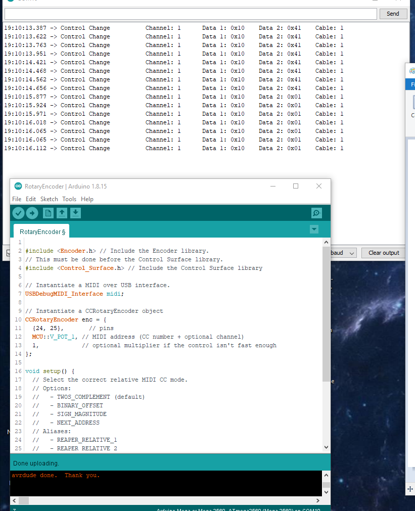
this code mess with the encoders rotation detection, jump over some ticks and very messy using. the button are working perfectly, from encoers themseves or other buttons.

if y remove the 5v pin from the encoder, they suddenly act properly but the 2 directions merge into one direction.

and if i use simple non midi, just staying in dfu alt mode with the simple encoder code, the encoder make perfect +4 or -4 per tick. even if i swap to midi mode removing pin connection, the falue red on the sequencer is ok.

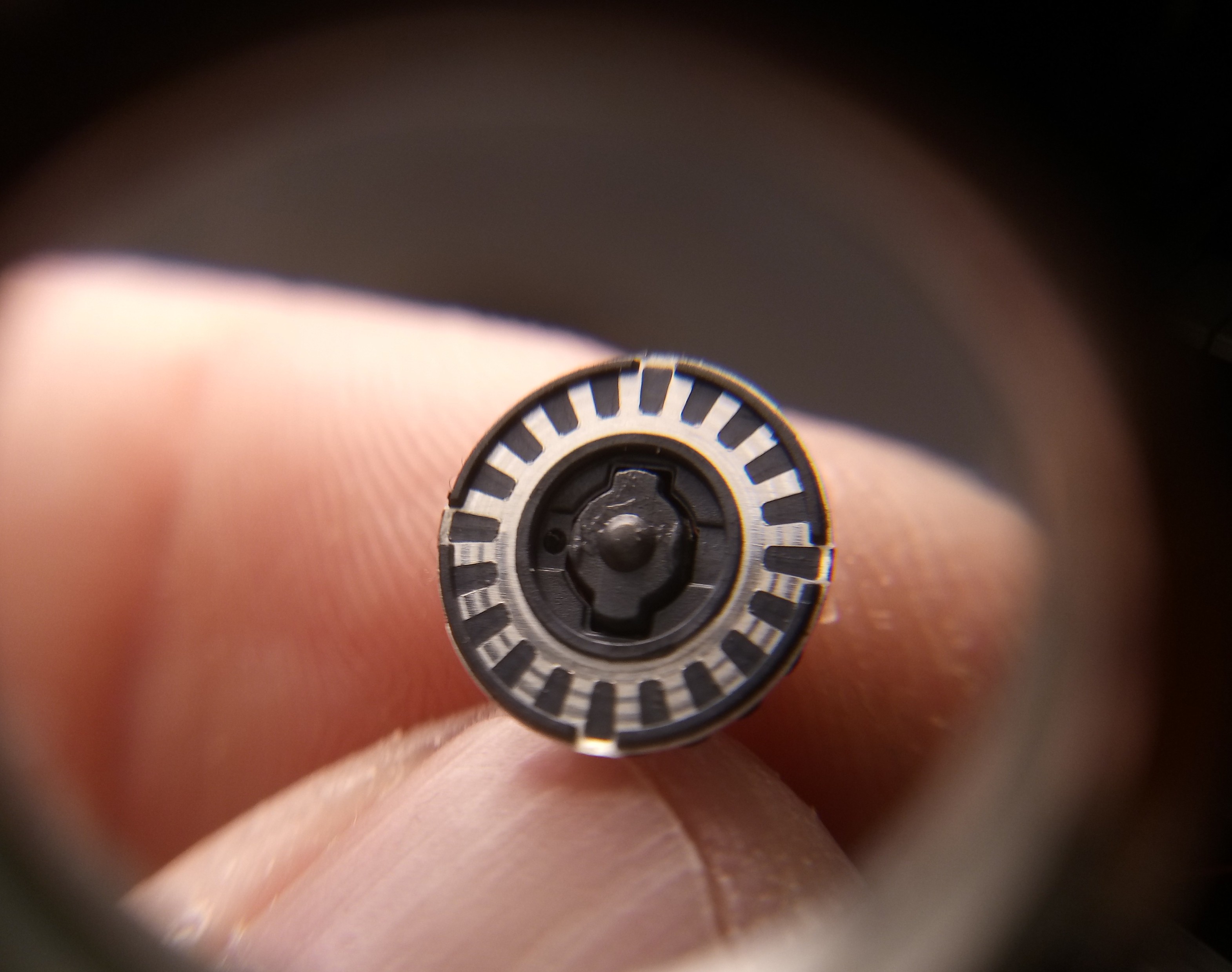
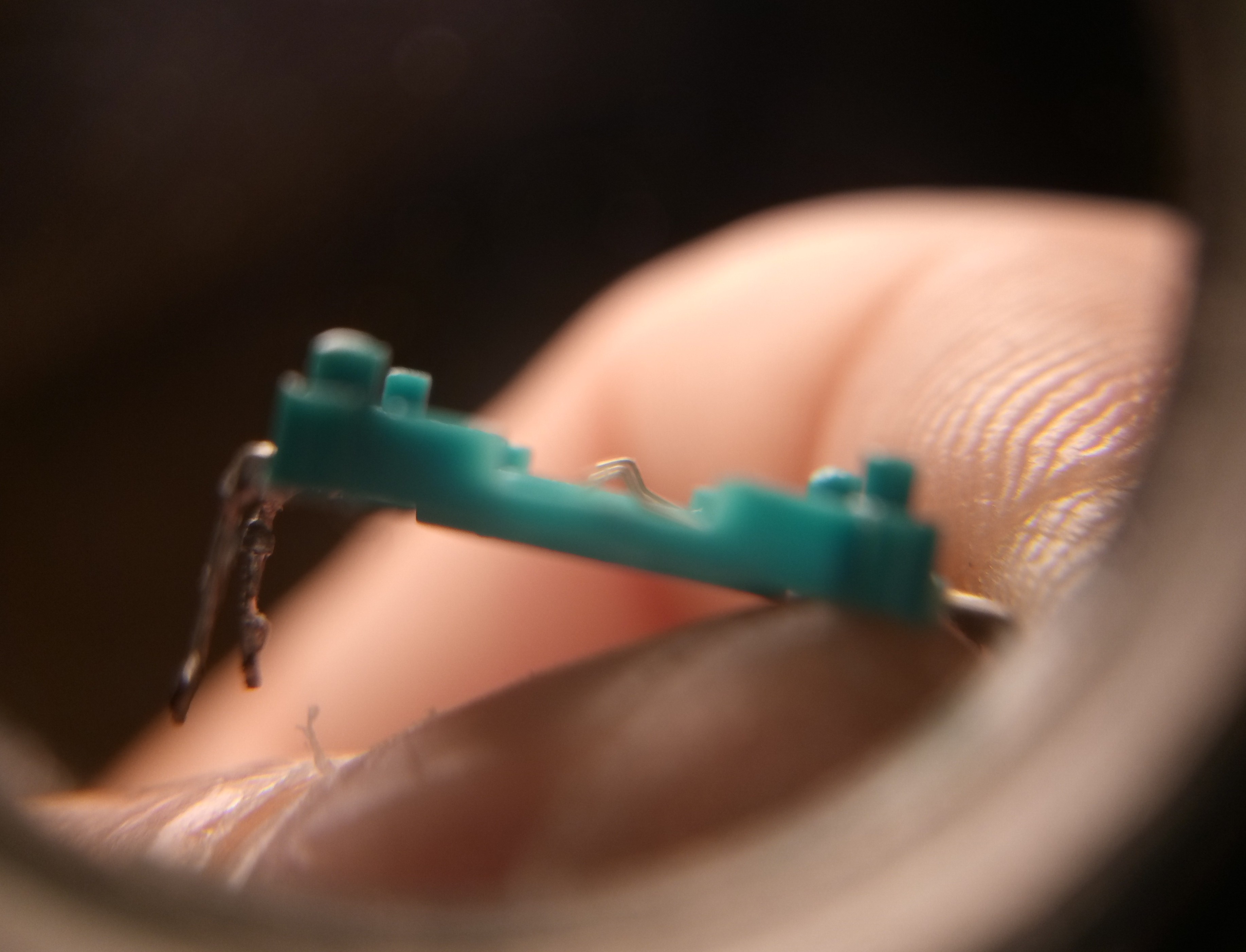
so in the final deduction of mine there is a serious issue on the debounce section of the code with the hardware i have, an arduino mega and C11encoder, end they works just fine by themselves.

i tried the notes and volte code but the pultiplexer is not working, and there is no encoer on his code, i do not know how to code, but by observing, and modding, i go step by step and start to understand how it works, but i am into a wall of knowledge i cannot overpass at the moment.

You forgot a semicolon after midi.

I think the problem is the amount of buttons you're trying to read. Especially through a multiplexer, that takes quite a bit of time. Since you're not using interrupt-capable pins, the encoders will be polled at a rate that's too low to capture all pulses.

Does the code work if you get rid of all buttons and multiplexers? Or if you keep only a single encoder (like the RotaryEncoder example).

i missunderstood what you asked, i applied the test on the code i use instead of the exemple :stuck_out_tongue:

this code


#include <Encoder.h> // Include the Encoder library.
// This must be done before the Control Surface library.
#include <Control_Surface.h> // Include the Control Surface library

// Instantiate a MIDI over USB interface.
USBMIDI_Interface midi;

// Instantiate a CCRotaryEncoder object
CCRotaryEncoder enc = {
  {2, 3},       // pins
  MCU::V_POT_1, // MIDI address (CC number + optional channel)
  1,            // optional multiplier if the control isn't fast enough
};

void setup() {
  // Select the correct relative MIDI CC mode.
  // Options:
  //   - TWOS_COMPLEMENT (default)
  //   - BINARY_OFFSET
  //   - SIGN_MAGNITUDE
  //   - NEXT_ADDRESS
  // Aliases:
  //   - REAPER_RELATIVE_1
  //   - REAPER_RELATIVE_2
  //   - REAPER_RELATIVE_3
  //   - TRACKTION_RELATIVE
  //   - MACKIE_CONTROL_RELATIVE
  //   - KORG_KONTROL_INC_DEC_1
  RelativeCCSender::setMode(relativeCCmode::MACKIE_CONTROL_RELATIVE);
  Control_Surface.begin(); // Initialize Control Surface
}

void loop() {
  Control_Surface.loop(); // Update the Control Surface
}

give me this on midi side by just making one tick

01

That doesn't look right at all. Please try the USBDebugMIDI_Interface and post the output from the Serial Monitor.

fully working.

the only thing remaining is, it works on dfu arduino but once i revert to the midi mode the data is corrupted or improper.

i try to get the mega recognized by flip to revert to the factory behavior but it seems not to work as intended, i am chasing the issue to be sure there is no problem with the dual boot, this is the only last remainng test to do