Well if you're going to put it into saturation with no heatsink what do you expect !
This should work using existing components. Need to invert logic on Arduino pin.


raschemmel:
That is low but I think it's time we asked for some empirical data.
yup. this whole thread is based on the assumption that the heater was designed to be 25 watt and that it was designed to run on 12 volts. Not a 125 volt heater that the user only wants to run at 25 watts.
when the results do not match the calculations, two choices, investigate the implementation ( I always assume I wired the circuit wrong) and also the fundamentals.
anyone know anything about this heater ?
I added a heatsink to the TIP120. It's warm as expected. Was looking at a mosfet. I had to order a logic level as I cannot source one locally.
The heater in question is as follows:
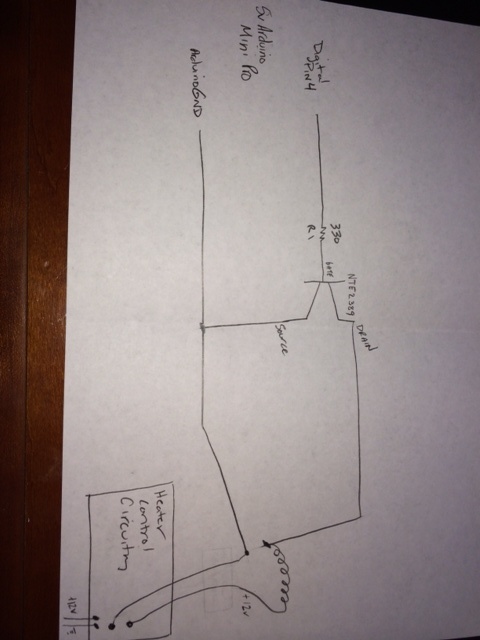
It is sourced with a 12v wall adapter. The 12v feeds an existing control board. There is an existing heater control board that controls the heat based on set point temp. What I am attempting to do it essentially bypass the existing control, by raising its thermostat to the maximum, thus making it want to constantly heat so that I can control it with my arduino. I have cut the negative side of the return wire. Here is a little better picture of what I am trying to do. If I test continuity of the where the heater connects to the board, I get continuity between the +12v of where the heater connects to the existing board and the +12v incoming from the wall wart. I do not get continuity from the ground side of the heater to the ground side of wall wart feed. What I am trying to do is pretty unorthodox I realize. THe main problem I think is that I do not know what the existing control circuitry is actually doing. The MOSFET I am showing in the drawing is not the correct one. i ordered some logic level MOSFETs I should have them in a couple days.
dlloyd,
Yes, that is precisely how I got it working. I added a heatsink it the TIP did get pretty warm as expected. I was trying to elminate the TIP120 and go with a mosfet is where I am with it.
raschemmel:
- VBE = 2.5V <--- voltage drop base to emitter for Ic = 5 Amp.
Ok. I got it. Yeah , that does change things ...
so we have the Arduino pin at 4.1V --> 330R --> 1.5V at the base for Ic = 1 Amp.
Since the OP said the heater wasn't getting hot enough then maybe he was wrong about the max current. Maybe it is really way more than 0.4A. He hasn't given us any current measurement data and actually that's why he posted in the first place so we have to assume that if he begins his post by stating "I want to measure the heater current" he should follow it by the statement "I THINK the max current is 0.4A but don't assume that is correct. " Since the heater did not get hot enough with the 330 ohm resistor then I think we can assume the current is greater than 1A and your calculation above is no longer valid. Now we should consider:
- VBE = 2.5V <--- voltage drop base to emitter for Ic = 5 Amp.
Let VBE = 2.5v
Let VB = 0.9V
Let V (out:arduino)=5V
Then 5V-2.5V-0.9V=1.6V
1.6V/330=0.0048A=4.8mA
That is low but I think it's time we asked for some empirical data. I haven't seen any voltage measurement data from the OP .
Now he is using the 2n2222 to drive darlington directly so we need the V(base) voltage (2n2222 VE).
It would be nice if we could get the 2n2222 collector current. That is what we really need.
And yes, your right, a MOSFET is a much better tool for the job.
The component I am trying to control is a small incubator, which the manufacturer states it is a 25 watts. The supply is a 12v wall wart, so it would be around 2 amps is my best guess. I can get any data that would help. I can provide the collector current, I will check it when I get home tonight. I had to order some logic level MOSFETs as it seems the concensus to be the best solution. I ordered them yesterday. I can measure the collector current of the current setup and post that once I get home. Thanks!
he component I am trying to control is a small incubator, which the manufacturer states it is a 25 watts. The supply is a 12v wall wart, so it would be around 2 amps is my best guess.
So you are now confirming that the previously stated 400mA in not valid ?
Current Calculation:
Using P = V2/R, 25=144/R, R = 5.76 OHM
Using V = IR, 12=I5.76, I = 2.08 Amp
If using the FKI10531 MOSFET, note that the gate voltage at which it starts to turn on is typically 2.0V and it will be completely turned on at VGS = 4.5V. Controlling it with 4.1V should not be a problem and it should run cool enough. It's possible to put a 330 ohm pull-up on the Arduino which would increase the drive voltage but I don't think this will be required.
MOSFETs with lower gate drive voltages are available, however they're surface mount type.
Current Calculation:
Using P = V2/R, 25=144/R, R = 5.76 OHM
Using V = IR, 12=I5.76, I = 2.08 Amp
Of course, why didn't I realize that : (that the Votage & Power were KNOWNS. (DUH !) .and you can solve for the UNKNOWN (heater resistance) I should have caught that. I feel stupid. ( I just realized that I confused this post with another that also involve a heater and the current on that one was 400mA). Thanks for getting me back on track. If someone had asked to calculate the current given the voltage and power I wouldn't have hesitated for a second, but I never really identified which were KNOWN and which were SPECULATION. Thanks Dlloyd. Sometimes we need someone to slap us on the side of the head and say WAKE UP !
Robert
I use need coffee ... (lots of it).
dlloyd: Yes, I see. Thank you for making known the why and the how. I have a lot to learn.
Now hopefully I ordered the correct MOSFETS, which is the next point of confusion, trying to read the datasheets. I looked at the one for FKI10531that you mentioned: http://www.semicon.sanken-ele.co.jp/sk_content/fki10531_ds_en.pdf
Under Features it says Qg ----9.0nC(Vgs = 4.5V, Vds = 50V, Id = 11.9A). But down below under Maximun Ratings it says Vgs +- 20 V. Trying to compare this sheet to the FQP30N06L LOGIC N-Channel MOSFET that I bought: http://dlnmh9ip6v2uc.cloudfront.net/datasheets/Components/General/FQP30N06L.pdf
It is difficult to determine to the uneducated what all of that means. I chose the one I got because it was a LOGIC driven, and Sparkfun sells it on their site being able to be turned on fully directly from a microcontroller pin. Looking at the graph, it does not appear it will be completely fully on at 4.1 volts. What I am trying to understand is how to make sense of these. What are the critical points in a datasheet that I need to know? It's giving me a dang headache.
Robert: but..but..but I never said 400mA. Seriously tho half of what you guys said went over my head, which is good, it forces me to learn which is always a good thing. I was lacking some key information and I see the error of my ways.
Thanks a lot!
VectorSix, the MOSFET you ordered looks pretty good to me. From the graph (Figure 2) it looks like only 4V drive will allow 30 Amps to be switched. A rough calculation gives an ON resistance of 0.13 ohm. Since you're switching only 2A, it will dissipate only 0.5 watts and would not require a heat-sink.
You should have no trouble with this one - good luck!
The 3.5 ma to 35 ma range is not the range of my sensor. The heater on my o2 sensor will draw between 100 and 400 mA, my BIG QUESTION is: How can I use the INA169 to sense within this range??
Dlloyd,
Here's the post from the OTHER POST that confused me and made me think the OP said something about it being 400mA.
TO EVERYONE ELSE: THE ABOVE QUOTE HAS NOTHING WHATSOEVER TO DO WITH THIS POST !
This is working perfectly with the MOSFET I ordered. I can't even feel it dissipating any heat. So ditching the 2N2222 and TIP120 for the logic level MOSFET was definitely the way to go. Can run it directly from the pin. Thanks for the help fellas.
I can't find the place where someone recommended a gate resistor. Are you using one ?
10K from common control pin to common ground, yes. However I was planning to drive that with an optocoupler to maximize isolation.