hi , i am working on a project that required a specific speed of 5.74mm/min for the linear actuator.....my actuator does not have a build in potentiometer for feedback things. I am operating it with a BTS7960B H-bridge motor driver . I did tried so many codes to make it run with 5.74mm/min, but i could not .
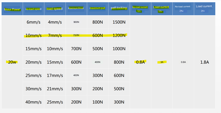
The no load speed of my actuator is 10mm/s and the load speed is 7mm/s........ please can anyone suggest me a solution
PID requires feedback, in this case, the speed of the motor.
can you add an encoder?
1 Like
i have a displacement sensor , i don't think encoder is proper for a linear actuator since we don't have an access to the dc motor inside right ?
how i can add an encoder to the dc motor , since the dc motor is inside the actuater
now i see, it's a very slow speed. so the target position is constantly changing.
i would start with a simulation on a laptop. the I term could maintain a constant speed while the error remains zero. in other words it anticipates the change in position
The displacement sensor can be used to estimate the speed of extension, but that can likely only be done in coarse steps, meaning that the PID loop time will be slow and the control erratic.
It would be best to sense the motor speed somehow.
What signal do you get out of the displacement sensor?
an analog signal
Is that the very best you can do?
Good luck with your project.
i dont know do you have any suggestion ? because i am very confused that my doctor in the university told me that you can only use a pid controller to have this very low speed , i asked him if i need another sensor he said no !!
Unfortunately my experience are very low , i don't know how to do such a thing , i only know the basic of using an Arduino and controlling the PWM ... the thing that this is very low speed as u said and i cant use a low PWM just to reach it , but i need a PID controller
If your advisor knows how to proceed, ask him for guidance. That is his job.
You have given us no useful information about your equipment.
1 Like
Can i use an encoder as sensor for the linear movement of the actuator ? because i searched about it and it turn to be it measure the rotation things like a tachometer,, and in my case i have a linear movement
Build a servo using the "analog signal" as a servo potentiometer, and use the PID to drive the "BTS7960B H-bridge motor driver", then use the 5.74mm/min rate to periodically set the SetPoint of the PID.
Supposing the "analog signal" ramps from 0 to 1023 in for 100mm total displacement, then it's 1024/100=10.24counts/mm to move the thing by 5.74mm/min you need to move the setpoint by 5.74mm/min *10.24 count/mm = 58.7776count/min, or `60sec/min*1000ms/sec/(58.7776count)= 1021ms/count.
That's all I've got. Goodnight & good luck.
Could you please give more explanation
what was the answer to this?
1 Like
How long is your actuator?
What does the analog sensor read at the limits of travel?
What is your schematic?
Do you have code that reads your analog sensor? Please share.
Do you have code that drives your motor? Please share.
sounds like you're not familiar with PID: proportional, derivative, integral
given an measurement and a target, there is an error = target - measurement.
one component is error * Kp, the proportional result. but this requires that there be some error. this really wouldn't be a solution if trying to maintain motor speed because ideally the error would be zero by you still need a non-zero output to drive the motor
but the integral term can help with this. it accumulates a portion, Ki, of the error resulting in a non-zero output after the error becomes zero. this might be helpful in your case. if the motor gets ahead of itself, is beyond the target position, the error becomes negative. the proportion terms subtracts from the integral term slowing the motor down, and the accumulated error is reduced resulting in a smaller integral component of the output
ideally, the integral output is exactly the motor PWM needed to maintain the speed of the motor with zero error
the derivative component, usually of speed. while driving a car up to a stop sign, people slow down as they approach the stop sign. so while the proportional term results in opening the throttle, the derivative term, the speed is subtracted resulting in a negative component that counters the proportional term resulting in lower speed closer to the target (stop sign)
i don't see a need for Kd in this case (Kd = 0)
again, trying to test your understanding without the target hardware would be helpful
1 Like
https://www.instructables.com/DIY-Servo-Motor/ demonstrates how to make a servo out of a DC motor and a pot.
I had an Wokwi simulation simulating the physics of a DC motor, and I edited it a bit to make a simulated servo out of it:
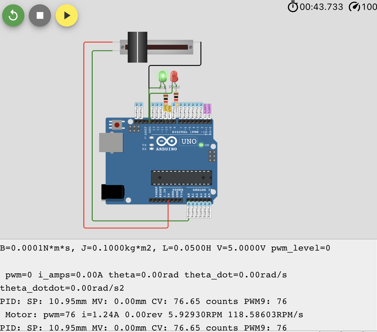
- The top slider sets the setpoint of the process at 0-100mm
- The simulated motor drives a simulated linear actuator from 0-100mm, with the simulated process measurements and motor variables measurements printed in the serial monitor
- The LEDs show the PWM signal and the direction signal that is being fed into the simulated motor.
There are many configurable parameters, from motor inertia and friction, to the translation of turns of the motor into linear distance, and the code is rough and untuned, but it demonstrates the process of making a servo out of a PID controlled DC motor with an analog distance sensor.
You are welcome to play around with it to see how bi-directional dc motor might move an actuator, how that might move an analog sensor, and how one might use the actuator output to change the motor inputs with a PID.
What I like about this simulation is that the simulated motor gets its inputs through the PWM pin and direction pin.
I think the sim shows a way to do the first and second parts of this suggestion, and the third part would be like simulating sliding the pot at the desired speed.
Your hardware would be different. Good luck.
here's a crude simulation
cyan/orange distance
green/violet speed
red/yellow error
both sets have a Kp of 1.8.
the cyan/green/red has a Ki of 2.0
note that the error (red) is near zero and distance (cyan) larger (more correct) with the Ki term

the sim models motor as directly proportion to the pid output which is a very gross estimate that doesn't account for motor inertia