Controlling a vertical plotter with Accelstepper and AFMotor

Hi, i”m making a vertical plotter powered by an arduino uno with an Adafruit v1 motor shield. It consists of 2 NEMA 17 stepper motors spaced about 350mm apart. The steppers are connected to a “pen” with a GT2 rubber belt.

I’m currently trying to make it draw a straight line, but since the motors have the same speed and acceleration, the lines are not straight when the amount of steps each motor has to take is different. Currently, the following values define the motors speed and acceleration: stepper1.setMaxSpeed(200); stepper1.setMaxAcceleration(150.0); stepper2.setMaxSpeed(200); stepper2.setMaxAcceleration(150);

Eventually, i want a function that takes a distance and angle. and moves the steppers to that position.

Any help on this would be greatly appreciated.

(below in red: the line the plotter has drawn, in blue: the line i want the plotter to draw)

For synchronised 2D-motion you can use the Bresenham-algorithm.

this might be interesting too

best regards Stefan

The ancient L293 drivers are not appropriate drivers for the modern current controlled bipolar stepper motors. Drivers like the DRV8825 are much more efficient and are made to control those motors.

This is true.

The TMC2209 driver-chip offers even more performance and a very silent running steppermotor
https://www.mouser.de/ProductDetail/Trinamic/TMC2209SILENTSTEPSTICK

best regards Stefan

1 Like

Thanks for the quick replies, I really appreciate it. Although (from what I can tell, so please correct me if I'm wrong) the algorithm above is great, for a xy-plotter. I don't know how I could implement in in a polargraph or vertical plotter.
Any help would (again) be greatly appreciated.

I had to ask Google what a polargraph is and he said it was drawing based on POLAR coordinates, not rectangular coordinates. What do you think a straight line is in polar coordinates? It is a curved line like when you fly from NewYork to Honolulu, you fly a curve.
So likely your red line is a correct straight line if you convert back to rectangular coordinates.

So instead, i should convert the rectangular coordinates I use as input, to polar coordinates to get it to draw a straight line between two points in rectangular coordinates.

Don't ask, try it.

rectangular and polar coordinates can be converted back and forth with some still relative simple formulas.

So far you have only shown a picture of the drawing result you got with your actual code.
You haven't explained how your mechanic is working. Best thing would be to post a picture how your mechanic looks like.

I estimate your mechanic is XY-axles and then the easiest way to get controlled motion is to use the bresenham algorithm.

You wrote

If the two motors have a different number of steps to do the speeds are different!!.

If you want to have a straight line the ratio how many steps in X-direction and how many steps in Y-direction has to be constant. dY / dx has to be constant.

If you use acceleration the acceleration-phase can be different long and this causes the effect you see on the paper: a curved line.

If you disable acceleration this might work more or less. Because by disabling acceleration the speed-ratio dY / dX stays the same from the very first step to the very last step.

The stepper-motors have to be kept in sync for a straight line. Regardless of the straight-lines direction. Even for vertical lines or horizontal lines the two stepper-motors have t be kept in sync.
For a vertical line keep X-motor at speed zero for all Y-steps (= they are synchronised to each other

unsynchronised would mean at some y-steps x-steps are zero and at other y-steps x-steps are non-zero. That would be out of synchronisation

And the only way to keep the two axles in sync is to create the step-pulses of both axles inside **one single ** loop.

And that is what the bresenham algorithm is doing. If you use the bresenham-algorithm you can use acceleration because the timing changes always in synchronisation for both axles.

Using two different function-calls like
stepper1.move(Xsteps)
stepper2.move(Ysteps)
with acceleration are completely out of sync

with acceleration set to zero
they are not really synchronised.

best regards Stefan

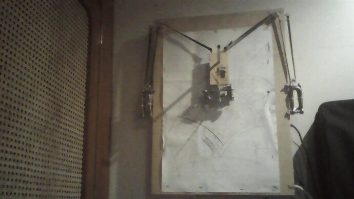
This is a picture of my current setup.

(Separate messages because I can only post one image per message.)

The same in pygame simulation of my plotter (I use this for testing).

As seen in the top picture, the movement of the pen relies on the use of weights. So without acceleration, every time the plotter suddenly stops, the weight swings a bit causing a slight offset from the target position. I'm not familiar with controlling steppers in this way, and also not familiar enough with mathematics to figure out the conversions from a cartesian plane to polar coordinates to synchronized stepper motion.

the bresenham-algorithm is for cartesian XY-axles. The synchronisation is done through

one loop

that creates the setp-signals for both motors.
as an easy to follow example if you have a slope of 0,5.
This means every two steps in X you do one step in Y.
one step x
onestep x and one step y
one step x
one step x and one step y
...

so in programming this would be

for (int i = 1; i < = 100; i++
  stepx(); //with each iteration do a X-step
  if ( i % 2 == 0) { // only if division by 2 has remainder zero 
    stepY  // do a Y-Step
  } 
}

bresenham calculates the slope. The axle that has the bigger value becomes the leading axle because more step-pulses must be created and the slower axle just creates a step if adding a fraction goes across the next digit before the comma

example for slope 0,25
y = 0,25 one step X
y = 0,5 one step X
y = 0,75 one step X
y = 1,0 one step X y-digit goes up before decimal-point => one step Y
y = 1,25 one step X
y = 1,5 one step X
y = 1,75 one step X
y = 2,0 one step X y-digit goes up before decimal-point => one step Y
....
If you have a slope bigger than 1 example slope 3
Y becomes the leading axle
x = 0,33 one step Y
x = 0,67 one step Y
x = 1,00 one step Y digit before decimal poit goes up => one step X
x = 1,33 one step Y
x = 1,67 one step Y
x = 2,00 one step Y digit before decimal poit goes up => one step X
...

that is the way bresenham works.

Now you have a very different mechanical system.
If you don't have a ready to use project there is no way around doing the calculations from cartesian xy-coordinates to changing toothbelt-lengths

Learning this will be a real great exercise how learning at university works.
Starting at a really low knowledge-level learning basics on the subject, proceeding further and further.
A part with try and error a part with tests and analysing the results.
This process includes to ask all kinds of epxerts:

  • books
  • articels
  • online-ressources
  • experts for motion-control
  • forum-users

you can take time to work it out. There is no timelimit like in an examination
you can ask all kinds of experts etc.
And this way you will make it work and you will be well prepared to the learning style of universities where others will do the first steps when arriving at the university.

You should click the "solved" button again to make the thread unsolved. As it is not yet solved
or start a new thread with a different title.

best regards Stefan

So I did some googling

https://www.google.de/search?q=vertical+plotter++arduino+sketch

and found this
https://create.arduino.cc/projecthub/fredrikstridsman/stringent-the-15-wall-plotter-d965ca

which has a link to the software

best regards Stefan

This topic was automatically closed 180 days after the last reply. New replies are no longer allowed.