I'm working on a project where I would like to control up to 5 3V coin micro vibration motors individually. The idea is to have them vibrating in a sequence, turning on and off one after the other.
I have multiplied the circuit and tested with 3 motors so far. The problem is that it is only the circuit connected to pin 3 on the Arduino that turns on.
Does anyone have any ideas to why the other circuits are not turning on and/or if there is a problem with the circuit itself and how it is powered?
I would be very grateful for any help or leads on this.
Amongst the problems with your arrangement there, are the fact that you are apparently using IRF520 FETs which are not logic-level in the first place, and you are driving them with a voltage divider so they probably do not all turn on due to a spread of individual parameters.
This circuit might work with transistors, but not those FETs.
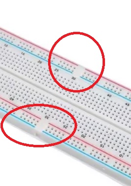
Yes, I'd suggest the same, gaps in breadboard bus bars - a trap for the unwary (the gaps are
great for RC filtering sections of power rail which is what they are presumably for.)
One lesson to learn - use a multimeter to check for voltages, any new circuit test that power is getting
to every device that needs it. Your eye's can't see voltage!
wvmarle:
How much current do those motors take? Chances are you can run them using a TPIC6B595 shift register, without the need for external transistors.