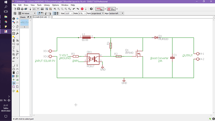
hello everyone, i am a student college and have already problem about my final project about boost converter. When i connect the circuit in projectboard with source from solar PV and then i have been measuring the voltage input and the ouput of capacitor (with no load), the output has been succesfully to boost the output voltage, but i dont know while i measuring the voltage input from solar pv in the circuit, it will very drop and reading on 6 volt, eventough the original input voltage solar PV (without connect to circuit) is 17 volt. in my opinion this drop caused by the resistor from optocopler R1 connect to source from solar pv to the inductor, but how to i can remove / change this circuit to keep it working?
.
im so very thankful if u want to help me ![]()
![]() May Allah reward you with a goodness :'')
May Allah reward you with a goodness :'')
.
this is a picture of the circuit :
PV cells are best considered to be current sources, rather than voltage sources, and they don't work well or at all with boost converters.
Without PWM from the Arduino Q1 is ON and current is limited only by the resistance of L1. This makes Q1 turn ON and OFF at an arbitrary frequency or hang at some current. Shorting PWM to GND will turn Q1 OFF and current is limited by L1+R1.
Does that change when you change the PWM?
Building a switch mode voltage regulator from discrete components isn't easy. It's normally done with a special purpose chip, or if you are not required to build your own you can buy a board or module. Most hobbyists buy something pre-made because even with the special chip it can be difficult to get it working properly.
A "normal" switch mode regulator (or DC-DC converter) does NOT have a microcontroller of software. They use a "special kind" of PWM that's generated internally (usually by the specialized chip) and controlled with feedback.
It is easy to make your own linear regulator with something like the LM7805, but linear regulators are inefficient (energy is wasted as heat) and you generally can't get much current out of them.
You are on the right track posting the schematic immediately it helps all of help you. However, the details are missing such as resistor values and voltages. Your MOSFET is on the cusp with a +- 20 Vgs rating. Consider placing a diode from X3-1 to X4-1 it will power the load when the MOSFET is on. I am assuming this is a school learning project not a product design.
okay thank you so much for your advice ![]()
thank you so much for your advice ![]() i will trying to thinking again about it
i will trying to thinking again about it ![]()
yes Sir, it will drop when i connect a solar PV to the circuit that pwm arduino has been connected to switching a mosfet.
Thank you so much for your advice ![]()
okay i will try it to thinking again about it... i'm so sorry, i'm still too basic for this and seem like learning project ![]() , but ya idk my lecturer give me a recommendation for this final project. ya i hope after this it can be work properly... thankyouu..
, but ya idk my lecturer give me a recommendation for this final project. ya i hope after this it can be work properly... thankyouu..
thank you so much for your advice, okay i wil try again to think about it ![]()
This topic was automatically closed 180 days after the last reply. New replies are no longer allowed.
