Well it printed gfeda when I just put the snippet into the original code. Sdrawkcab.
At the very least if direct port manipulation is used it won't need so many contikulous pins.
a7
Well it printed gfeda when I just put the snippet into the original code. Sdrawkcab.
At the very least if direct port manipulation is used it won't need so many contikulous pins.
a7
Awww I just got it. Sorry @alto777 ![]()
Thanks everyone for your reply.
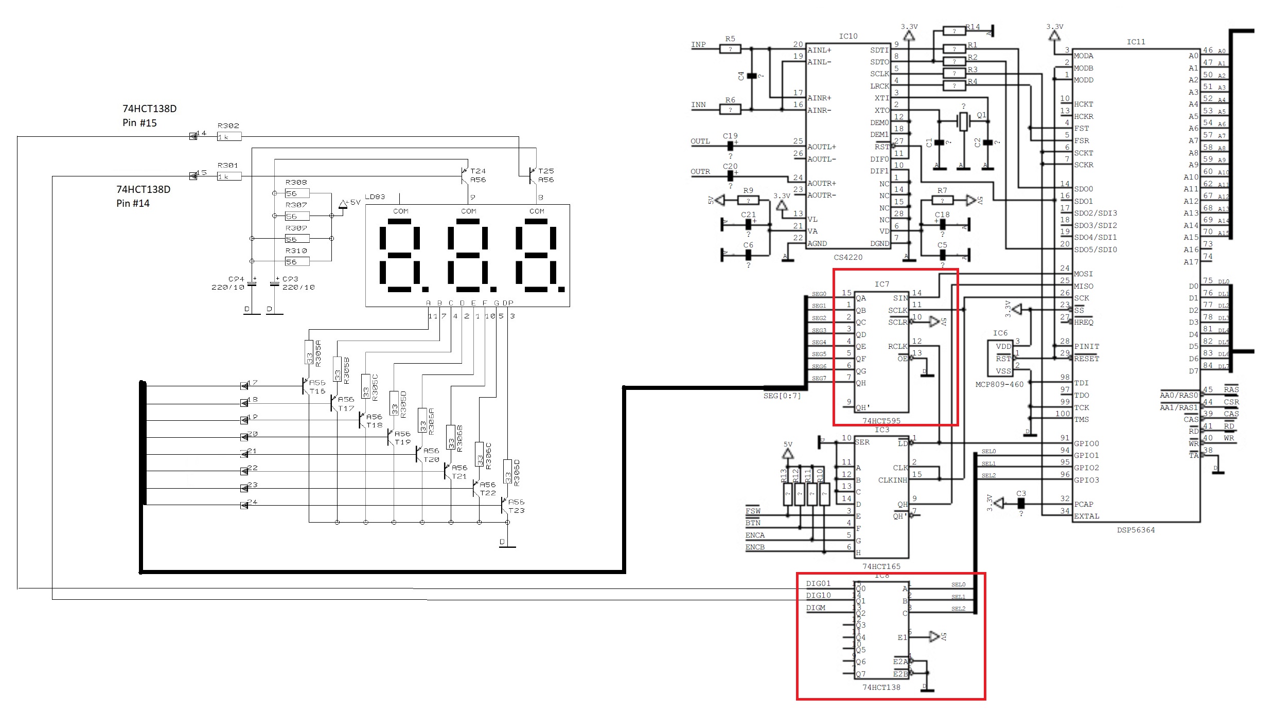
I managed to find the schematics and redraw/stitch them so everyone can view it easily, kindly refer to attached screenshot. So the 7-Segment driver is a 74HCT595 and the DIG01/DIG10 switcher is 74HCT165. So I believe there are two options, either to get the signal from the 7-Segment LCD Outputs or from the two ICs Inputs. Not sure which one is preferable. Looking forward to your expert advise and code.
Correction: So the 7-Segment driver is a 74HCT595 and the DIG01/DIG10 switcher is 74HCT138.
Additional info for IC 74HCT138 in the schematics and looking at the function table in attached screenshot. Since only pins 14 &15 are only used to drive the DIG01 and DIG10 in the 7-segment LCD, so I believe it is only input A0 that is used on this IC.
It's really between the input to the IC and the output from the IC, which is the same signals you'd pick off the segments.
It would be fun to take the serial input and collect it just the same as that IC does.
I think it would be easier, if you have 7 inputs, to just grab the segment data.
Or as has been shown above, just 5 inputs will do in this case.
Watch the digit select lines and/or whatever clocks them to know when to grab 5 segments and which digit that will mean you have just acquired.
a7
Can we be clear here. Is the reference to an LCD a typo?
Do you have in fact an LED?
There is world of difference between reading the two types.
Anyways, looking again at the schematics. I now suspect that IC 74HCT165 ( 8-bit parallel-in/serial out shift register) is the one supplying the number data to the 74HCT595. Hopefully this IC provides the full un-multiplexed data. But I have to figure out how can I hook its serial output (QH - Pin 9) to the Arduino NANO and show it to the OLED Display. Again need your expert advise and code if possible.
That is not involved with the LCD LED display. It appears to be used to interface a rotary encoder.
The '595 is where you can grab 5 segment values. From its outputs. That drive the LED segments.
The '138 is where you should observe the digit select signal. On its outputs.
One of DIG01, DIG10 and DIGM will transition to become the only one that is LOW (or is it the only one that is HIGH?), and that tells you what digit is being selected to energize.
That's when the 5 segment signals ADEFG should be read in. The value may be inverted to the way we've been using it to figure out the corresponding digit.
In a loop, wait to see one of digit selects go low then grab the segments and print.
As a first stab, just trying to read one of the digits, and not decoding the segment aggregate value. Yet.
Later - watch to see a digit selected, grab the segments and decode it and print the digit.
Then you should be ready to rock and roll.
a7
They are, but to control if a segment is on or off with an LED, all you have to do is to run a current for the segment. And to read it back all you have to do is to detect a voltage across the LED segment.
On an LCD to make a segment is on or off you have to put a multiple voltage waveform through it. Like this:-
And to detect if the segment is on or off you have to read the complex multi level voltages on the segment and decide if they are on or off.
The fact that they are both seven segment displays is quite irreverent when it comes to interfacing, as detecting those sorts of waveforms requires a LOT of electronics.
Note you need one of the circuits in Fig XI for every segment.
Further note that this applies to only one sort of LCD, they are not all like that.
@CoJammer I have coded a rudimentary analyser as I began to describe in #31 above.
Try it here:
If you can make use of it, it should allow you to figure some things out. Maybe some enhancements to my hack will suggest themselves to you. I would be happy to hear about that and maybe help.
If it all make no sense, you may prefer to take up knitting as a hobby. Or at least dial back what you can expect from yourself at this point. Nothing I did is particularly hard once it is easy. ![]()
// https://forum.arduino.cc/t/converting-2-digit-multiplexed-7-segment-led-signal-to-128-x-64-oled-using-arduino-nano/1129222
// https://wokwi.com/projects/365887839415838721

// https://docs.arduino.cc/hacking/software/PortManipulation
// https://www.arduino.cc/reference/en/language/functions/external-interrupts/attachinterrupt/

const byte ledPin = 7;
const byte interruptPin = 2;
volatile byte state = LOW;

unsigned char iGlag;

void setup() {
  Serial.begin(115200);
  Serial.println("breakfast oscilloscope v0.0\n");

  pinMode(ledPin, OUTPUT);
  pinMode(interruptPin, INPUT_PULLUP);
  attachInterrupt(digitalPinToInterrupt(interruptPin), blink, CHANGE);

  DDRB  &= 0b11100000;   // inputs 8 to 12
  PORTB |= 0b00011111;   // weak pullup
}


// watch for either edge
// wait a bit and grab 8 - 12 inputs
// when you've seen both edges, print a report about them
// reset and repeat

// In this simulation, bouncing on the switch has been turned off!
// we do not expcet bouncing on the observed signals

unsigned char edgesSeen;
unsigned char portOnEdge[2];   // 0 - rising edge, 1 - falling edge

void loop() {
  digitalWrite(ledPin, state);

  if (iGlag) {
    unsigned char onPortB = PINB;
    iGlag = 0;    // clear the flag
    delayMicroseconds(15);    // why not?

    if (digitalRead(interruptPin)) {
      portOnEdge[0] = PINB & 0b00011111;
    }
    else {
      portOnEdge[1] = PINB & 0b00011111;
    }
    edgesSeen++;
  }

  if (edgesSeen >= 2) {
    Serial.print("segments after clock rises ");
    Serial.println(portOnEdge[0], BIN);

    Serial.print("segments after clock fallls ");
    Serial.println(portOnEdge[1], BIN);

    Serial.println();

    edgesSeen = 0;
  }
}

void blink() {
  state = !state;
  iGlag = 1;      // set the flag
}
HTH
a7
You may need to delay a small amount of time between the transition of DIG01/DIG10/DIGM and reading the segment data. To prevent ghosting it is common to have all the LED segments turned OFF when the transition occurs. (Ghosting is where an LED digit has a dim image of the number being displayed on an adjacent digit, caused by the change in segment data not occurring simultaneously with the transition between digits).
Yes. In my hack, I
delayMicroseconds(15); // why not?
before the segment lines are grabbed. I had that there for riding past contact bounce, for which 15 ms would have been more like it. Then I switched off the bounce feature of the pushbutton in the simulator and TBH don't know what I had in mind leaving the delay, or even if it was originally milliseconds.
15 us seems like an eternity. Obvsly waiting too long runs into the limit you can wait due to the refresh rate. If the refresh is 500 Hz, each digit is energized for most of 666 us (check my maths), so that delay could be way larger. The refresh rate is probably much lower.
I got confused trying to see if the segments and digit selects are active high or low and went to the beach. I am sure someone can read the schematic and say what the sense of those signals is for sure.
a7
Actually, this rotary encoder is the one that tells the DSP56364 what Sound Effect to use. Rotating it will change the value of the 7-segment LED Display. I want to try this method first as I believe taking signals from the 7-segment LED, plus the multiplexing DIG01, DIG10 is quite complicated.
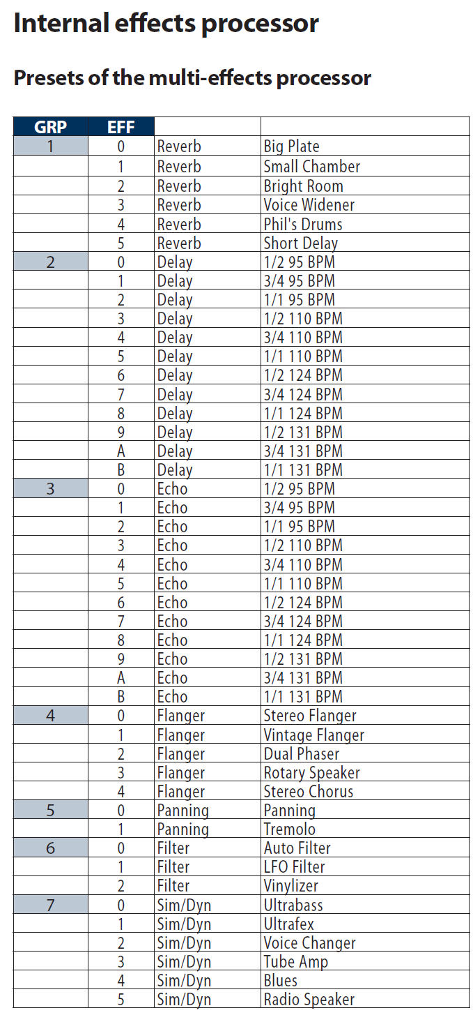
The existing 2-digit 7-segment numeric LED is just showing the number of equivalent effect as shown on the table below:
What I want the 128 x 64 OLED display to show is two lines of text from above table - equivalent to the number the existing numeric 7-segment LED is showing:
Line 1: EFFECT Name (e.g, Reverb, Delay, Echo, etc.)
Line 2: Current EFFECT Variation ( Big Plate, Small Chamber, Bright Room, etc.)
I have been searching through Arduino projects on the Internet that are similar to this application and already tried stitching them together with Frankenstein approach (I am an Arduino lizard, not wizard) , but those projects include sub-menus that are too complicated to be stripped down into a simple 2 lines to display a total of 46 array of texts to be browsed in the OLED Display. I don't think I even need the pushbutton of the rotary encoder. Hopefully the Arduino Nano have enough resources to handle this array of texts.
Hope the Gurus in this forum can show me a code, or guide me on how/where to start.
Thanks and Highly Appreciated . . .
I've just quickly reviewed, so I may be totally wrong but...
If you hijack the rotary encoder and take the same steps it does, you would still have to know where the device directly controlled original was in its list.
With luck, the device powers up in its first position, then you'd only have to be sure to never miss a pusle from the encoder, and that both you and the device agree how many clicks per step.
As always, it comes down what kind of fun you want to have. I will say the encoder path seems easier to get working, but be prepared to be disappointed if it doesn't work so good in practive.
a7
This topic was automatically closed 180 days after the last reply. New replies are no longer allowed.