4 digit 7 segment display driver

This is all just an experiment to see what I can do with a display I bought by accident. I took a sketch from an old forum discussion and modified it. I didn't know if I would see an output since the input part of the sketch needs lots of work, meaning I don't know how to go about it.
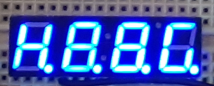
What I see is H.8.8.G.
I'm just trying to find a use for this extra piece of hardware by experimenting.

/* Name       : 4x7 display
   Author     : Philip Minch
   Originator : adapted from sketch by brys912
   Created    : 2025-05-15
   Modified   :
   Version    : 1.0
   Driving 4-digit, 7-segment LED display
   through a 74HC595 shift register
*/
// connections to NXP 74HC595N shift register IC:
int dataPin = 9;   //74HC595  pin 14 DS
int latchPin = 10; //74HC595  pin 12 STCP
int clockPin = 11; //74HC595  pin 11 SHCP

// connections to YSB-439AB-4B-35 digit enable pins
const int digit1 = 7;  // display pin 1, ones place common cathode
const int digit2 = 8;  // display pin 2, tens place common cathode
const int digit3 = 12; // display pin 6, hundreds place common cathode
const int digit4 = 13; // display pin 8, thousands place common cathode

const int digitPins[4] = {7, 8, 12, 13}; //array for digit drive

unsigned char table[] =
{ 0xFC, 0x60, 0xDA, 0xF2, 0x66, 0xFE, 0xF6, 0xEE,
  0x3E, 0xB6, 0xBE, 0xE0, 0x9C, 0x7A, 0x9E, 0x83, 0x00
};
/* this table has drivers for digits 0 to F and blank
  Element  0   1   2   3   4   5   6   7   8   9  10  11  12  13  14  15  16
  Value   FC  60  DA  F2  66  FE  F6  EE  3E  B6  BE  E0  9C  7A  9E  83  00
  Digit    0   1   2   3   4   5   6   7   8   9   A   B   C   D   E   F (none)
*/

void setup() {
  Serial.begin(9600);
  pinMode(latchPin, OUTPUT);
  pinMode(clockPin, OUTPUT);
  pinMode(dataPin, OUTPUT);

  pinMode(digit1, OUTPUT);
  pinMode(digit2, OUTPUT);
  pinMode(digit3, OUTPUT);
  pinMode(digit4, OUTPUT);
}

void Display(unsigned char num, int digitDisplay)
{

  digitalWrite(latchPin, LOW);
  shiftOut(dataPin, clockPin, LSBFIRST, table[num]);
  digitalWrite(latchPin, HIGH);

  digitalWrite(digitPins[digitDisplay], LOW);

  for (int k = 0; k < 4; k ++) {
    if (k == digitDisplay)
      continue; // iterate until k == value of digitDisplay
    else
      digitalWrite(digitPins[k], HIGH);
  }

}
void loop() {

  // integerSensor = 222; (I don't know what this is)
  Display(2/*integerSensor%10*/, 3);
  delay(1);
  Display(4/*integerSensor%100*/, 2);
  delay(1);
  Display(3/*integerSensor % 1000*/, 1);
  delay(1);
  Display(12, 0);
  delay(1);
}

Here's the board layout:

 aaa
f   b
f   b
f   b
 ggg
e   c
e   c
e   c
 ddd dp

0110111 0x37 H
1111111 0xFF 8
1111111 0xFF 8
1011111 0xBF G

Probably incorrect wiring.

Try to find the model number of your 4x7seg and then find its datasheet. Find the "common" (Anode or Cathode... looks like Cathode, but verify). Your drawing also has some floating components (not touching any holes or wires).

We need to know the part number of your display. Is it the same as the one mentioned in the code comments?

We need to know the part number of the transistors you are using.

Are the lit segments equally bright?

I would say it looks like common anode because the transistors are switching 5V to the common pins. If it was common cathode, the display would not light at all. Assuming the digit common pins and segment pins have been correctly identified, that is...

I'm thinking that if those transistors are PNP, then because the code is sending HIGH to one of their base pins and LOW to the other 3 base pins, the result would be that 3 digits out of 4 are lit at any instant instead of only lighting 1 digit out of 4. If that's true, the segments will show a blend of 3 merged segment patterns, and not all segments will be equal brightness.

I was in too much of a rush with the hex digits and some of them are incorrect. I will post the corrections.

Yes, the display part number is in the sketch. It is supposedly like this:

The board layout was made in Visio, I don't have fritzing. The "floating" parts mentioned might be the resistors with a gray line for the leads.

The transistors are RadioShack antiques without part numbers. General purpose NPN.

As for this comment:
0110111 0x37 H
1111111 0xFF 8
1111111 0xFF 8
1011111 0xBF G
Add a final 1 for the decimal point.

Yes, This picture is a bit deceiving as the unlit segments look to be dimly lit. They are not.
image

This may be clearer than the board layout.

…as long as it’s wired properly, this is what should be included with most posts !

Many thanks

I’m a bit concerned about the NPN transistors in the +v leg of the displays ?

You can use this library, or refer to the code of it: GitHub - DIYables/DIYables_4Digit7Segment_74HC595: The Arduino library for 74HC595 4-dot 4-digit 7-segment display. It works with Arduino, ESP32, ESP8266.

That combination of hift register and display looks nice, but it isn't what I'm working with. If I could see the internals of it I might be able to duplicate it externally.

Here's the updated character table. The decimal point circuits are wired, but not in the character table. I only need to add 1 if I decide to display it.

unsigned char table[] =
{ 0xFC, 0x60, 0xDA, 0xF2, 0x66, 0xB6, 0xBE, 0xE6,
  0xFE, 0xFA, 0xEE, 0x3E, 0x90, 0x7A, 0x9E, 0x8E, 0x00
};

I'm not keen on it. I didn't want to run the digits directly to limit Arduino output current.

The 470 ohm resistors limit the segment current. Using PNP transistors would be more desirable, but would require inverting the segment drive logic.

Since you are using npn transistors I believe that the LOW and HIGH below should be interchanged, similar to the comment by @PaulRB, to ensure only one digit is active at any one time:

The original code looks like it was intended for pnp transistors.

Remember that the shift register is connected to the display cathodes. A LOW output from the shift register will light a segment, a HIGH output will switch the segment off.

You are right. When I said

I was misreading the code. The code is correct for PNP (one pin low to switch on a digit). It needs reversing for NPN.

Also, because the NPN are being used in emitter-follower configuration, I seem to remember that the base resistors are not necessary because the base current will be self-limited (based on the emitter current and the transistor gain). The disadvantage of using NPN as emitter-followers is that the voltage drop will be much higher than if PNP were used (~0.7V Vs ~0.2V). This could be more of an issue because the display uses blue LEDs which have a higher forward voltage than red LEDs. However, that doesn't seem to be a problem in this case, the display looks bright enough in the photo.

Yes, what you've said about the emitter follower configuration is correct and, in this case, tho OP gets away with it. If, however, the MCU pins were 3.3v instead of 5v it would mean only about 2.6v at the display anodes which may not be enough.

I see my dumb mistake with H and L now.
I think I will change the circuit with a second shift register for digit select and I won't need to sequence digits.
Then I can use a separate source for displays.

Having changed the table to switch H and L, I get partial success. On reset, digit #3 of the display strobes 4 times, then displays 8888. Subsequent resets go through the procedure with the other 3 characters. At least they are the characters I expected to see.

Since the digits aren't sequencing, I think it's time to change to my other idea of a second shift register for digit control.

True, but a safety factor in case of miswiring. Too much base to emitter voltage lets the smoke out explosively. Don't ask how I know.