I saw this before but it didn't register.
Here is what I ordered, is it the right one?
I saw this before but it didn't register.
Here is what I ordered, is it the right one?
Here is what I ordered, is it the right one?
Say what?
forgot the product number!!!!!!!!!!!!
US5881LUA-AAA-000-BU
Seems like it should do the job.
See figure 12.3
PDF reference https://www.mouser.com/ds/2/734/US5881-Datasheet-Melexis-953437.pdf
It is important your design assembly have no sloppiness to have repeatable dependable operation.
I working to get my display working. My code is attached. I'm getting an error message That Matrix not defined. I'll also include the sample code that works fine.
Sample code:
/***************************************************
  This is a library for our I2C LED Backpacks

  Designed specifically to work with the Adafruit LED 7-Segment backpacks
  ----> http://www.adafruit.com/products/881
  ----> http://www.adafruit.com/products/880
  ----> http://www.adafruit.com/products/879
  ----> http://www.adafruit.com/products/878

  These displays use I2C to communicate, 2 pins are required to
  interface. There are multiple selectable I2C addresses. For backpacks
  with 2 Address Select pins: 0x70, 0x71, 0x72 or 0x73. For backpacks
  with 3 Address Select pins: 0x70 thru 0x77

  Adafruit invests time and resources providing this open source code,
  please support Adafruit and open-source hardware by purchasing
  products from Adafruit!

  Written by Limor Fried/Ladyada for Adafruit Industries.
  BSD license, all text above must be included in any redistribution
 ****************************************************/

#include <Wire.h> // Enable this line if using Arduino Uno, Mega, etc.
#include <Adafruit_GFX.h>
#include "Adafruit_LEDBackpack.h"

Adafruit_7segment matrix = Adafruit_7segment();

void setup() {
#ifndef __AVR_ATtiny85__
  Serial.begin(9600);
  Serial.println("7 Segment Backpack Test");
#endif
  matrix.begin(0x70);
}

void loop() {
  // try to print a number thats too long
  matrix.print(10000, DEC);
  matrix.writeDisplay();
  delay(5000);

  // print a hex number
  matrix.print(0xBEEF, HEX);
  matrix.writeDisplay();
  delay(5000);

  // print a floating point
  matrix.print(12.34);
  matrix.writeDisplay();
  delay(5000);

 // print with print/println
  for (uint16_t counter = 0; counter < 9999; counter++) {
    matrix.println(counter);
    matrix.writeDisplay();
    delay(10);
  }

  // method #2 - draw each digit
  uint16_t blinkcounter = 0;
  boolean drawDots = false;
  for (uint16_t counter = 0; counter < 9999; counter ++) {
    matrix.writeDigitNum(0, (counter / 1000), drawDots);
    matrix.writeDigitNum(1, (counter / 100) % 10, drawDots);
    matrix.drawColon(drawDots);
    matrix.writeDigitNum(3, (counter / 10) % 10, drawDots);
    matrix.writeDigitNum(4, counter % 10, drawDots);

    blinkcounter+=50;
    if (blinkcounter < 500) {
      drawDots = false;
    } else if (blinkcounter < 1000) {
      drawDots = true;
    } else {
      blinkcounter = 0;
    }
    matrix.writeDisplay();
    delay(10);
  }
}
Just noticed my code was not attached - oopps!
counter_mph.02.ino.ino (7.72 KB)
The library example contained this code which I do not see in the attachment.
#include <Wire.h> // Enable this line if using Arduino Uno, Mega, etc.
#include <Adafruit_GFX.h>
#include "Adafruit_LEDBackpack.h"

Adafruit_7segment matrix = Adafruit_7segment();
Thanks Cattledog, I swear I had that in there so never went back to look! The Hall effect sensors should be hear later today.
I got the Hall effect sensors late yesterday. I have it hooked up to a breadboard and it works as long as I put it to pin 2. My problem is I have a button hooked to pin 2. How would I change this to pin 4? Here's the test code:
/*
Arduino Hall Effect Sensor Project
by Arvind Sanjeev
Please check out  http://diyhacking.com for the tutorial of this project.
DIY Hacking
*/


 volatile byte half_revolutions;
 unsigned int rpm;
 unsigned long timeold;
 void setup()
 {
   Serial.begin(9600);
   attachInterrupt(0, magnet_detect, RISING);//Initialize the intterrupt pin (Arduino digital pin 2)
   half_revolutions = 0;
   rpm = 0;
   timeold = 0;
 }
 void loop()//Measure RPM
 {
   if (half_revolutions >= 20) {
     rpm = 30*1000/(millis() - timeold)*half_revolutions;
     timeold = millis();
     half_revolutions = 0;
     //Serial.println(rpm,DEC);
   }
 }
 void magnet_detect()//This function is called whenever a magnet/interrupt is detected by the arduino
 {
   half_revolutions++;
   Serial.println("detect");
 }
Pin 2/3 can be used as interrupt pins, pin 4 cannot.
However, don't use interrupts.
Suggest you treat the 'Hall sensor' as you did the 'photo transistor', i.e. as a simple switch.
Then use the code I posted a while back.
My problem is I have a button hooked to pin 2. How would I change this to pin 4?
I think you are using a UNO with external interrupts on pin 2 and 3. There are also pin change interrupts available on all the general I/O pins. I think that your options are
use polling like larryd suggests
Move the button to pin 4 and place the Hall sensor external interrupts on pin 2.
Use a pin change interrupt on pin4. There is no simple IDE equivalent to attachInterrupt() for pin change interrupts. This means you are is best served with a pin change interrupt library unless you want to learn some of the lower level register commands required to implement the pin change interrupts.
There are several pin change interrupt libraries available and I like the one from Nico Hood in that the syntax is complely analagous to what you have learned with attachInterrupt(). It is available through the library manager, and there is additional documentation available at GitHub - NicoHood/PinChangeInterrupt: A simple & compact PinChangeInterrupt library for Arduino
attachPCINT(digitalPinToPCINT(4), magnet_detect, RISING);
I hope you are using two magnets. If not, change the half_revolutions to something which reflects the actual numbe of magnets you are using.
Remove the serial printing from the magnet_detect ISR. Serial printing requires interrupts, and they are disabled within the ISR.
Ok, that is easy enough. I just change the buttons to 4 & 5. That will leave 2 for this one and 3 for another should I need it.
Thanks
This project is dealing with slow devices, don't use interrupts.
.
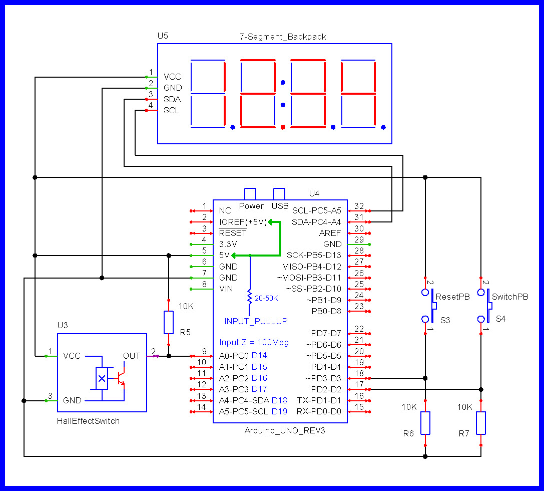
Larry, you just answered my next question with your diagram. (as as I was getting the soldering iron out.)
Don't forget 4.7k pullup resistors on SDA, SCL if the display lacks them.
Display seems to be working fine.
Seems that the faster I sweep the magnet the more accurate it gets. I'll be going real slow when I'm using the counter. Do I place the magnet farther away for more acuracy?
Seems that the faster I sweep the magnet the more accurate it gets. I'll be going real slow when I'm using the counter. Do I place the magnet farther away for more acuracy?
Are you using the code from post # 35?
What does "more accurate" mean?
Yes the code from 35. As far as the more accurate - If I pass the magnet slow past the sensor it will read (1 1 1 1) if i move it fast it will read (1 2 3 4). Maybe it could have to do with the timer?
The code in #35 is reading transitions. The hall sensor is a latching switch. The timer period for checking the count is 10 seconds. You will see a count display of 1-1-1 with an unchanging count if it takes 30 seconds to move the magnet slowly before the sensor as the output switches from off to on to off again as the magnet moves past.
That is what you want. You want to count the transitions. The time of the magnet in front of the sensor is only a fraction of the time for a rotation of the wheel.
The code is designed to count the number of times the magnet passes in front of the sensor in a time period. For slow rotations, you may need to adjust the time period to be much longer than 10 seconds to include several transitions.
The alternative approach is to determine the interval between every time the magnet triggers the sensor and calculate the rpm from the interval.
There are two ways to determine rpm. One is to count the number of rotations in a fixed time period, and the other is to determine the time period for one (or several) rotations.