#include <LiquidCrystal_I2C.h>
LiquidCrystal_I2C lcd(0x27, 16, 2); // LCD address and dimensions (16x2)
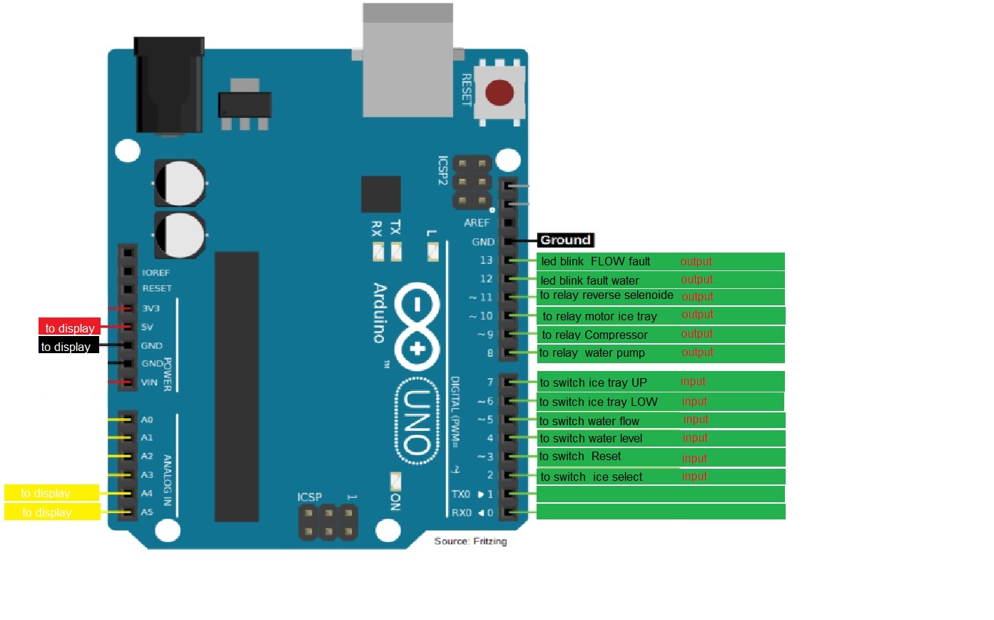
// Pin definitions
enum Pins {
pinButton = 2,
pinReset = 3,
pinWaterLevel = 4,
pinTrayHigh = 7,
pinTrayLow = 6,
pinWaterFlow = 5,
pinWaterPump = 8,
pinIceSolenoid = 11,
pinCompressor = 9,
pinTrayMotor = 10,
pinWaterShortageLED = 12,
pinNoFlowLED = 13
};
#define stopTrayMotor digitalWrite(pinTrayMotor,LOW)
// Tray motor direction constants
const int CW = 1; // Clockwise direction
const int CCW = 2; // Counterclockwise direction
const char getIceSizeName[3][7] = { "Small ", "Medium", "Large "};
const byte Time[3] = {3, 6, 9};
// Maximum motor direction change timeout (half a second)
const unsigned long motorDirectionChangeTimeout = 500;
enum State {
SETUP,
CHECK_WATER_LEVEL,
INITIAL_TRAY_POSITION,
SELECT_TIME,
FILLING,
COMPRESSOR_ON,
MAKING_ICE,
LOWER_TRAY,
RELEASE_ICE,
ERROR_WATER,
ERROR_FLOW,
ERROR_TRAY
};
unsigned long stateStartTime;
unsigned long iceMakingTime = 0; // Default time of 10 seconds
bool motorDirectionChanged = true;
unsigned long lastMotorDirectionChangeTime = 0;
State currentState;
int buttonPressCount = 0; // Variável de seleção
bool CountedDown = false; // Variável de contagem inicializada fora do switch
void setup() {
// Pin input/output configuration
for (int i = pinButton; i != pinNoFlowLED; i++) pinMode(i, 1 + (i < pinWaterPump));
// LCD initialization
lcd.init();
lcd.backlight();
// Start state machine at SELECT_TIME
currentState = SELECT_TIME;
}
void loop() {
switch (currentState) {
case SELECT_TIME:
lcd.clear();
lcd.print("Cube Size:");
stateStartTime = millis();
while (millis() - stateStartTime < 15000) {
if (digitalRead(pinButton) == LOW) {
buttonPressCount++;
if (buttonPressCount > 3) buttonPressCount = 1; // Closed cycle
lcd.setCursor(0, 1);
lcd.print(getIceSizeName[buttonPressCount - 1]);
}
delay(50); // Debounce delay
}
iceMakingTime = Time[buttonPressCount - 1];
lcd.clear();
lcd.print("Ice size: ");
lcd.print(getIceSizeName[buttonPressCount - 1]);
lcd.setCursor(0, 1);
lcd.print(iceMakingTime);
lcd.print(" seconds");
delay(2000);
iceMakingTime *= 1000;
currentState = CHECK_WATER_LEVEL;
break;
case CHECK_WATER_LEVEL:
if (digitalRead(pinWaterLevel) == HIGH) {
lcd.clear();
lcd.print("Water Shortage");
digitalWrite(pinWaterShortageLED, HIGH);
digitalWrite(pinWaterPump, LOW);
digitalWrite(pinIceSolenoid, LOW);
digitalWrite(pinCompressor, LOW);
stopTrayMotor;
while (digitalRead(pinReset));
digitalWrite(pinWaterShortageLED, LOW);
} else currentState = INITIAL_TRAY_POSITION;
lcd.clear();
lcd.print("COMPRESSOR ON");
digitalWrite(pinCompressor, HIGH);
delay(2000);
break;
case INITIAL_TRAY_POSITION:
lcd.clear();
lcd.print("RAISING");
runTrayMotor(CW); // Raise tray (clockwise direction)
stateStartTime = millis();
CountedDown = false;
// Wait for pinTrayLow to go HIGH (indicating tray is starting to rise)
while (!digitalRead(pinTrayLow)) {
if (millis() - stateStartTime > 6000) {
currentState = ERROR_TRAY;
return;
}
delay(100);
displayCountdown(stateStartTime, 6000);
// Check if pinTrayHigh is LOW before proceeding to FILLING
if (!digitalRead(pinTrayHigh)) {
stopTrayMotor;
currentState = FILLING;
return;
}
}
// If pinTrayLow is HIGH but pinTrayHigh is not LOW yet, continue waiting
while (digitalRead(pinTrayHigh)) {
if (millis() - stateStartTime >= motorDirectionChangeTimeout) {
currentState = ERROR_TRAY;
return;
}
delay(100);
displayCountdown(stateStartTime, motorDirectionChangeTimeout);
}
stopTrayMotor;
currentState = FILLING;
break;
case FILLING:
lcd.clear();
lcd.print("FILLING");
stateStartTime = millis();
digitalWrite(pinWaterPump, HIGH);
while (millis() - stateStartTime < 2000) {
displayCountdown(stateStartTime, 2000);
}
digitalWrite(pinWaterPump, LOW);
currentState = MAKING_ICE;
break;
case MAKING_ICE:
stateStartTime = millis();
lcd.clear();
lcd.print("FREEZING");
while (millis() - stateStartTime < iceMakingTime) {
displayCountdown(stateStartTime, iceMakingTime);
}
currentState = LOWER_TRAY;
break;
case LOWER_TRAY:
lcd.clear();
lcd.print("LOWERING");
runTrayMotor(CCW); // Lower tray (counterclockwise direction)
stateStartTime = millis();
CountedDown = false;
// Wait for pinTrayHigh to go HIGH (indicating tray is starting to lower)
while (!digitalRead(pinTrayHigh)) {
if (millis() - stateStartTime > 6000) {
currentState = ERROR_TRAY;
return;
}
delay(100);
displayCountdown(stateStartTime, 6000);
}
// Wait for pinTrayLow to go LOW (indicating tray is fully lowered)
while (digitalRead(pinTrayLow)) {
if (millis() - stateStartTime > 6000) {
currentState = ERROR_TRAY;
return;
}
delay(100);
displayCountdown(stateStartTime, 6000);
}
stopTrayMotor;
currentState = RELEASE_ICE;
break;
case RELEASE_ICE:
stateStartTime = millis();
lcd.clear();
lcd.print("RELEASING ICE");
digitalWrite(pinIceSolenoid, HIGH);
while (millis() - stateStartTime < 2000) {
displayCountdown(stateStartTime, 2000);
}
digitalWrite(pinIceSolenoid, LOW);
currentState = CHECK_WATER_LEVEL; // Voltando para CHECK_WATER_LEVEL ao invés de INITIAL_TRAY_POSITION
break;
case ERROR_WATER:
lcd.clear();
lcd.print("Water Error");
digitalWrite(pinWaterPump, LOW);
digitalWrite(pinIceSolenoid, LOW);
digitalWrite(pinCompressor, LOW);
stopTrayMotor;
while (digitalRead(pinReset));
currentState = CHECK_WATER_LEVEL;
break;
case ERROR_FLOW:
lcd.clear();
lcd.print("No Water Flow");
digitalWrite(pinNoFlowLED, HIGH);
digitalWrite(pinWaterPump, LOW);
digitalWrite(pinIceSolenoid, LOW);
digitalWrite(pinCompressor, LOW);
stopTrayMotor;
while (digitalRead(pinReset));
digitalWrite(pinNoFlowLED, LOW);
currentState = CHECK_WATER_LEVEL;
break;
case ERROR_TRAY:
lcd.clear();
lcd.print("Tray Error");
digitalWrite(pinWaterPump, LOW);
digitalWrite(pinIceSolenoid, LOW);
digitalWrite(pinCompressor, LOW);
stopTrayMotor;
while (digitalRead(pinReset));
currentState = CHECK_WATER_LEVEL;
break;
default:
currentState = CHECK_WATER_LEVEL;
break;
}
}
void displayCountdown(unsigned long startTime, unsigned long duration) {
unsigned long remainingTime = (duration - (millis() - startTime)) / 1000;
lcd.setCursor(0, 1);
lcd.print("Time left: ");
lcd.print(remainingTime);
lcd.print(" sec");
}
void runTrayMotor(int direction) {
if (direction == CW) {
digitalWrite(pinTrayMotor, HIGH);
motorDirectionChanged = false;
} else if (direction == CCW) {
digitalWrite(pinTrayMotor, HIGH);
motorDirectionChanged = true;
}
}
my words in my language:
CODIGO FINAL TESTADO NO SIMULADOR,
Apenas falta testar no real com o motor para ver se a reversao de rotacao funciona por pulso ( na da pra ver um led pulsar kkkkkkkk)
que esse codigo ajude os outros que nao finalizaram suas ideias, e que ajudem muitos mais, eu estou muito feliz
now in English:
FINAL CODE TESTED IN THE SIMULATOR,
All that remains is to test it in real life with the motor to see if the rotation reversal works by pulse (you can't see a pulsating LED hahaha).
May this code help others who haven't finalized their ideas, and may it help many more, I'm very happy