I have been working on this design for TinyISP programmer. Everything except for bootloader programming works. I can program via ISP, and serial com over a FTDI work. I can also program an ATtiny if one is attached.
The problem when doing programming over FTDI and the bootloader is, it acts like it isn't even there. I get the famous stk500_getsync() resp0x00 error.
Can someone take a look at the schematic and see if I missed something? I have been over 100 times and I can't see any problems. I have tried 3 Atmega328p and I know they work as I can put them in an UNO and they work fine, ISP and serial programming.
Another pair of eyes would be great. I have looked over the PCB and I can't see any errors from the FAB on it either. Originally I had a cap on the DTR line but for some reason that didn't work at all. So I removed it and shorted the line. I noticed on the oscope that reset is held low all the way through programming with my FTDI cable but programming an Arduino UNO its only held down for the beginning. But I can program other boards with the cable. So I guess either way is valid serial programming.
Maybe I should solder up a 2nd one to make sure it isn't the PCB.
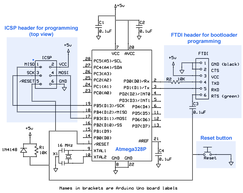
The FTDI DTR->Reset line normally has a 0.1 µF capacitor in series.
I usually put a 10K resistor between the FTDI pin and Rx (pin 3 on the Atmega) for current limiting.
Originally I did have the .1uf in series but I couldn't even program it over ISP till I removed it. I did have it closer to the ISP header than the DTR\RTS header.
I could try the resistor on the TX line when I get home. Its just strange since my other design works fine, only difference it is a TQFP ATmega328p.
What I did observe is that it is for sure in Reset. I took the IC out programmed the bootloader and blink sketch for pin 9 in my case. Then put it back and tried to serial upload and its stops blinking till I get the error.
So strange. So must a have to do with TX\RX?
They can't be backwards since I can see the monitor when I use TinyISP.
Yeah, this has got me stumped. I am going to have to move forward without the bootloader. In the end its not needed but still bothers me that it doesn't work. There is got to be something cause this. Flashing the bootloader sets the fuses so can't be a IC settings.
MobileWill:
Originally I did have the .1uf in series but I couldn't even program it over ISP till I removed it. I did have it closer to the ISP header than the DTR\RTS header.
This doesn't make a heap of sense. A 0.1 µF capacitor in series with a static signal cannot prevent it from being being programmed. There is no way that could keep reset asserted.
Well right now Reset is asserted without it during programming. But with it I couldn't do ISP. The first version of this PCB didn't have the reset pullup or .1uf in series. But I went back and tried that board and I couldn't serial flash either.
It has a nice 5v and 16mhz resonator. I have a ground plane on the top and bottom.
I updated the schmatic back the the original one that matches the board with the .1 in series. I should of post that first.
I tried doing ISP and it won't work with the .1 so I must have it in the wrong spot. It looks like I need to move it so that the ISP is on the other side of it.
Wow! It works! So the 0.1uf in series is required for serial programming. Now that it works I should look at the scope but it will probably be the same I should of hooked up the scope to the other side of the cap. So out of this I learned that the 0.1 uf is required and this is happens when you are doing this at 11pm and are in a hurry and looking in all the wrong places.
I cut the trace and soldered a wire from ISP pin 5 to the other side of the cap and it works
I couldn't of figured it out with out you.
PM me your address and I will send you one when I get the final design.
So can you explain to me what the cap does in series other than filter?
A picture really helps...
Note, R can be pull-up or pull-down configured... Don't get hung-up on the resistor. For uC reset use, just look at a half-cycle of the input waveform. http://www.electronics-tutorials.ws/filter/fil39.gif