Hey everybody, I'm trying to build my own customized button box. It will have 35 buttons on it, all of which will different functions. I was wondering what Arduino Board will be needed for this project. This is going to be used mainly for Euro Truck Simulator 2 and American Truck Simulator. Please help, this is my very first project.
Any LEDs etc.
No LEDs, only rotary encoders, push button, latching push button, and rocker switches. I should point out that I have no experience in coding what so ever.
What kind of 'functions' will this do?
What will be the purpose of this box?
.
Basically this box will do things handle engine controls on the truck, parking brake, trailer brake, and etc. The purpose of this box is to free up my keyboard and to create a more realistic gaming experience.
If only on/off switches, toggle switches (basically two ON switches) and push buttons a button matrix would be the way to go. 35 buttons can go in a 5x7 matrix so need 5+7=12 inputs, though toggle switches count for two so you may need to go for a 6x7 matrix if you have those as well (then it's 13 inputs for 42 total buttons).
This is also assuming no interrupts are needed, as interrupts and button matrices don't go together.
wvmarle:
This is also assuming no interrupts are needed, as interrupts and button matrices don't go together.
And consider that encoder performance is much improved when they're handled via interrupts. The more stuff the code is doing the more encoder responsiveness will suffer if only polled.
What about the rotary encoders? What will the matrix look like with the rotary encoders added on? I also noticed that there are things such as communication ports on some of these boards. Does any of that matter? Lastly does it matter what type of board I use for this box when it is connected to the computer via usb connection?
Oh, missed the encoders part. Those may better be handled separately indeed, while the other buttons ar escanned.
You should handle the encoders separately, any analog axes should be different too.
This is for an HID controller? An Arduino Micro has a USB-AVR chip that makes HID easy to code. A Micro with pins can plug into a breadboard or female connectors including DuPont Cable female jumper ends if you don't want a breadboard.
You might need a diode per button in the matrix to be able to read multiple buttons down at once correctly.
Yes, this is definitely an HID controller. I can also handle using a breadboard because I putting all of this in a 24cm x 32cm x 11cm junction box, so space is not an issue here. Can I wire the diodes in series with the buttons? I do have a basic matrix in mind. It kind of looks like this, http://www.kevinpeat.com/img/button_box_bb.png
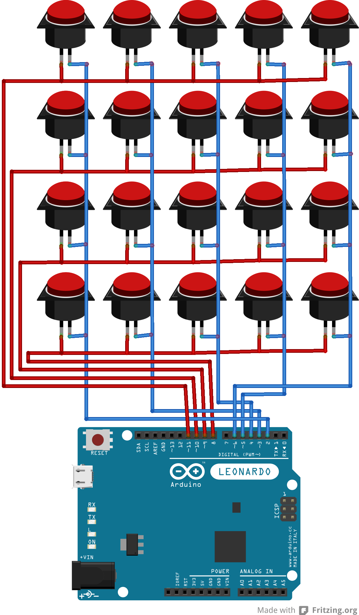
The diodes keep combinations of pressed buttons from allowing 1 wire to power other parallel wires (rows or columns).
I think that a .1uF cap across each switch would debounce the contacts. That's 35 diodes and caps, 2 solders each.....
With only 4 IO pins and a chain of parallel-to-serial input shift registers you can watch large numbers of buttons.
Look into capacitive touch sensors for Arduino (try Arduino Playground and Youtube). Make buttons from scrap metal and a few components that have no moving parts to wear out. The simplest I know uses 1 pin per sensor, works fast.