Okay, I'll explain it another way.
I don't know what your level of knowledge of basic electricity is.
To understand what I'm going to describe, you need to at least know Ohm's law and resistors in series.
E(V) = R(ohms) * I(Amp) OHM's Law
RT = R1 + R2 + R3. Resistors in series
Therefore, when the D1 manual says that the maximum voltage on pin A0 is 3.2 V (It should be 3V, but the difference will be within the tolerance of the ESP8266), it means that on the ADC pin of the ESP, you will have a maximum of 1 .07V.
Let's do the math:
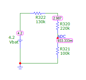
D1 internally has a resistive divider with 2 resistors in series of 200K and 100K, totaling 300K.
The 100K resistor goes between ADC and GND.
When connecting 3V to A0, 0.000010 A will pass through this series circuit.
By Ohm's law, we will have on the 100K resistor:
V = R1 * I = 100,000 * 0.000010 = 1V.
So in ADC we will have 1V, the correct value for the ESP8266 ADC.
If you connect a 4.2 V battery to A0, then a current of 4.2/300000 = 0.000014 mA will pass through the divider.
Again using Ohm's law, we will have a 100K resistor:
V = R1 * I = 100,000 * 0.000014 = 1.4V.
So in ADC we will have 1.4V, an incorrect value for the ESP8266 ADC.
But if you add an additional 120K resistor to the circuit,
it will have 420K and if you connect a 4.2 V battery to the end of this resistor, then a current of 4.2/420000 = 0.000010 mA will pass through the new divider.
Again using Ohm's law, we will have a 100K resistor:
V = R1 * I = 100,000 * 0.000010 = 1.0V.
So in ADC we will have 1.0V, the correct value for the ESP8266 ADC.
Now let's talk about the ESP ADC values in 10-bit resolution.
If you connect a 4.2V battery and do not use the additional 120K resistor, when the battery is fully charged, the voltage at the ADC pin of the ESP will be 1.4V (Incorrect value for the pin), but if it does not burn the ESP8266, the ADC reading will be 1023.
The reading will only be below 1023, when the value on the ADC pin is less than 1V, that is, in this situation when the battery has 3V, and the ADC value will be 1023.
From this battery value to zero, the value will be the ratio of 1/1023 = 0.002932551 for each decrease in the ADC value.
But the reading will be technically wrong.
But if you use the divider with the additional 120K resistor, then, when connecting a 4.2V battery to the end of this resistor, you will have 3V on the A0 pin, and 1V on the ADC pin and the ADC will have the value of 1023.
So when the battery, for example, has 3.6 V, in A0 you will have
2.5714 V and the ADC will have 0.8571 V, showing an ADC = 876.
Attached drawing for better understanding.