hi,
i need an analog input in my arduino mega 2560 to check my signal on oscilloscope,
how can i do this with my arduino?
Thank you,
Assy
hi,
i need an analog input in my arduino mega 2560 to check my signal on oscilloscope,
how can i do this with my arduino?
Thank you,
Assy
Your Mega already has an analogue input, but this is a little at odds with the title of this thread.
What exactly are you trying to do?
the DAC is a PWM signal but it can give analog values, not very precise on a scoop you will see a squarewave.
shooter:
the DAC is a PWM signal but it can give analog values, not very precise on a scoop you will see a squarewave.
DAC and PWM are completely different my friend. A DAC will actually output 0-5V and anywhere in-between while a PWM will oscillate from 0V to 5V NO IN-BETWEEN.
But as AWOL says, there is a problem between what your title says and what your post says...
DAC and PWM are completely different my friend.
No they are not. A filtered PWM IS a DAC. Because it converts a digital signal into an analogue one.
Grumpy_Mike:
No they are not. A filtered PWM IS a DAC. Because it converts a digital signal into an analogue one.
And if you don't filter it?
A DAC can be and usually is created using a resistor ladder, which is different from PWM.
Its like saying an analog pin is a digital pin. Its not, even if it can be used like one.
DAC types
The most common types of electronic DACs are:
The pulse-width modulator, the simplest DAC type. A stable current or voltage is switched into a low-pass analog filter with a duration determined by the digital input code. This technique is often used for electric motor speed control, but has many other applications as well.
Heh...deletes account
Thank you I appreciate it,
In my project I am doing a signal processing to a signal I convert the the signal to digital because I wanna transmit it to android smartphone using Bluetooth, the point it that I wanna check my code if the signal processing is working well do I want to see how it looks like In the ossiloscope.
I know that the arduino due has a dac pin..
But I can I see the analog signal in my board...?
Ps991 Spell Check Activated:
Thank you I appreciate it, .
In my project I am doing a signal processing to on a signal. I convert the the signal to digital because I wanna want to transmit it to an android smartphone using Bluetooth, the point it is that I wanna want to check my code to see if the signal processing is working well do . I want to see how it looks like In in the ossiloscope oscilloscope.
I know that the arduino due has a dac pin..
But I can I see the analog signal in my board...?
If the question is "can I read an analog signal with my arduino board?," then the answer is yes, you can. Connect your analog signal into any pin labeled A0, A1, ...
You can read them using the analogRead() function. The result will be 0-1023 on the arduino mega. 0 means 0V and 1023 means 5V, again on the mega.
I know that I can read an analog signal, the problem is that after I am doing a digital processing on my signal I wanna check it , to see if I did it well as I wanted to. And the osciloscope can get analog signals and the arduino gives digital so....
You need to be more specific. What kind of signal processing are you doing? What does the oscilloscope tell you? Can you not just compare general patterns between the 2 outputs? Can you not use an online calculator to perform the same function on a sample input?
I do not know what you are doing, what you want, what you expect, so I cannot help you.
When in doubt just spam your next thread with as much possible detail as humanly possible. VOMIT information!
I am doing IIR filter and the signal is an ECG signal that come from sensors on my body after they passed an analog signal processing they get to the Arduino.
the is a sinus signal.
Sorry bro, dont know...
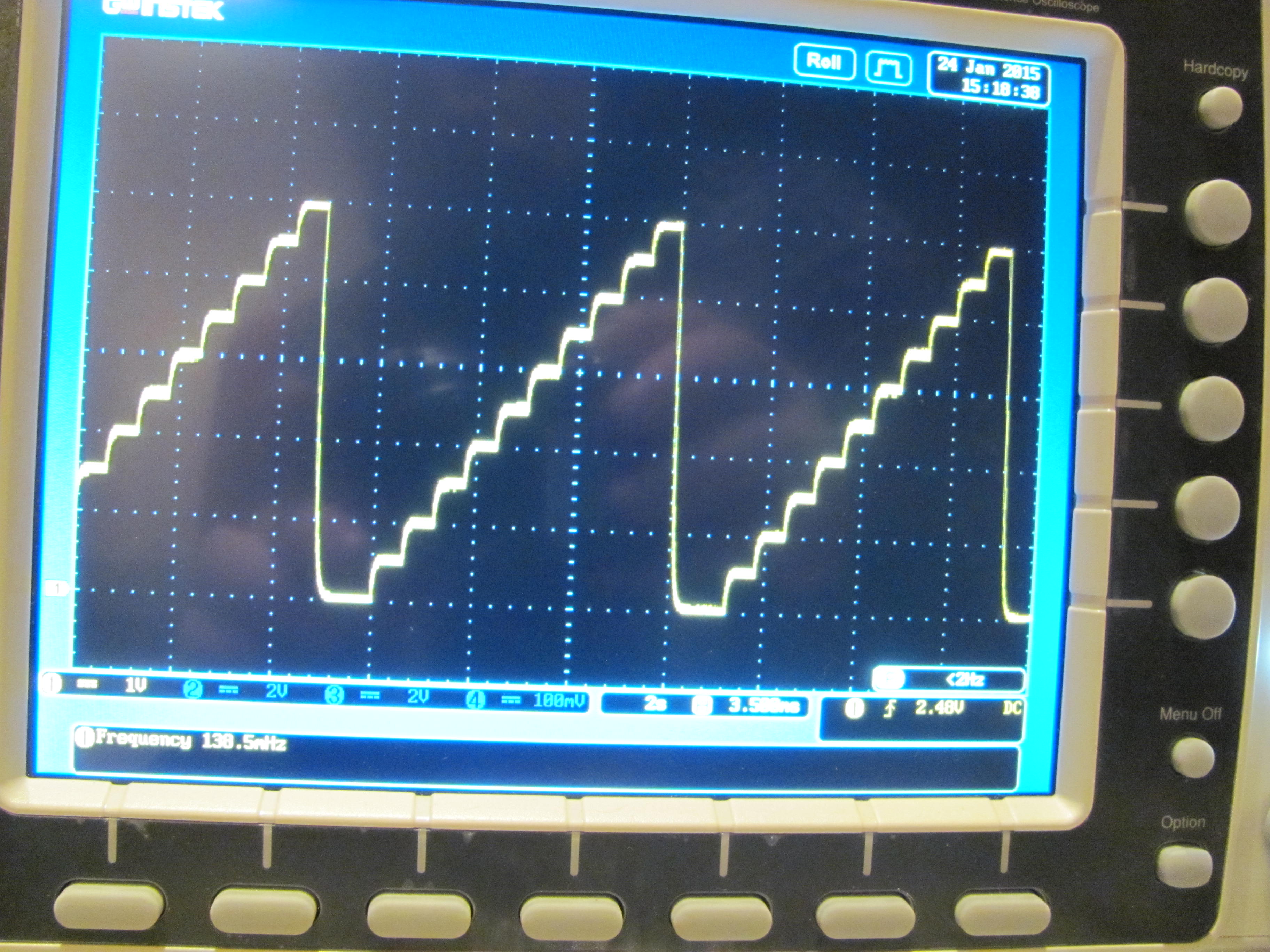
This signal ?

And after you perform your signal processing (IIR?) what do you expect? What kind of values do you want to see?
Because it looks to me like you can find the heartbeat by simply counting the spikes and comparing in over the amount of time it took to sample it...
yes
but my problem is how to output analog signal from the arduino (mega 2560) to the Osciloscope.
:o Thats it?! This whole time you keep saying "i need an analog input in my arduino mega 2560" when you meant to say "i need an analog output in my arduino mega 2560". You were wording your posts all wrong!
If you do not have an Arduino Due, then you will need to use a pwm signal with a low pass filter (something I learned today actually).
If you use a 4.7uF capacitor on your pwm output it will make your pwm look like an analog signal between 0-5V.
From wikipedia
The pulse-width modulator, the simplest DAC type. A stable current or voltage is switched into a low-pass analog filter with a duration determined by the digital input code. This technique is often used for electric motor speed control, but has many other applications as well.
Ok, thank you!
you have a drawing of the circuit \connections?
it really will help me to see hot to connect it...