Dashboard warning/indicator oled system, problems drawing bitmaps

Hi guys.

Just decided to sign up and post my first question- I have been trawling the internet for answers for so long and frustrations are running high.

My project is an extremely basic one by your standards- I simply have a small OLED screen displaying icons depending on which input is closed. I have deliberately kept my code very basic- I realize it is not as tidy or professional as it could be however it does work well in its most basic form.

The issues come when I try using the drawBitmap function. I have attached the basic sketch and associated .c file.

Basically, REGARDLESS of the information i place in that graphics.c file I only get a garbled mess pixels on the screen. The command itself works fine- start position and color of the drawing are reflected in what i see on the screen but the actual image itself is the identical layout of pixel mess no matter what bmp data i give it... I can remove the image part of my .c file without any change to what i see on the screen after upload... As if its not re-flashing what i have already burnt into progmem?

I hope this makes sense- hate to be another one of those people probably not providing enough info so please let me know if i missed anything out.

more info:
NANO,
128x128 color oled display,
all libraries etc work well except when using the bitmap function.

Thanks for any help & greetings from New Zealand.

bmptestlatest.ino (547 Bytes)

graphics.c (7.65 KB)

Welcome to the forum! Its much easier to view your code if you post it inline using the code tags (</>) as shown below.

Wondering if the code in graphics.c is actually being linked in at all? Maybe you can try to put it all in the main sketch file?

replace

extern uint8_t myBitmap[];

with

#include <avr/pgmspace.h>

const uint8_t  myBitmap [] PROGMEM = {
  // 'leftarrowtest'
  0x00, 0x00, 0x00, 0x00, 0x00, 0x07, 0xf0, 0x00, 0x00, 0x00, 0x00, 0x00, 0x00, 0x00, 0x00, 0x00,
 // etc etc
};

See if that makes any difference.

Otherwise have you tried any of these examples? Adafruit-SSD1351-library/test.ino at master · adafruit/Adafruit-SSD1351-library · GitHub in case you have made some kind of wiring error or have a faulty unit.

Hi there.

Thanks so much for your help.

I have tried the above however it fails to upload (compiles fine but has an error while uploading).

The wiring and stuff is good, I have had it working fine using the simple line command to draw the icons (however it gets pretty tiresome when you want to program icons which are more than 1 pixel wide lines)

Heres a video from a few weeks ago- I was pretty happy to even reach this point (i have changed to a larger screen since then, video was just to show a few people that i actually had something working)

If the code compiles then the only reason for an upload to fail would be a wiring problem, like it's not plugged in. Keep trying, or post the error message here. Use [ code ] tags for error messages too.

omg, embarrassing.

Yes, of course you are correct- i had recently unplugged the arduino cable from PC and plugged back into other port- had to change this in the software obviously.

#define sclk 13
#define mosi 11
#define cs   10
#define rst  9
#define dc   8


#define BLACK           0x0000
#define BLUE            0x001F
#define RED             0xF800
#define GREEN           0x07E0
#define YELLOW          0xFFE0

#include <Adafruit_GFX.h>
#include <Adafruit_SSD1351.h>
#include <SPI.h>


Adafruit_SSD1351 display = Adafruit_SSD1351(cs, dc, rst);


const unsigned char arrow [] PROGMEM = {
  // 'leftarrowtest'
  0x00, 0x00, 0x03, 0x80, 0x00, 0x00, 0x00, 0x00, 0x03, 0xc0, 0x00, 0x00, 0x00, 0x00, 0x03, 0xe0, 
  0x00, 0x00, 0x00, 0x00, 0x03, 0xb0, 0x00, 0x00, 0x00, 0x00, 0x03, 0x98, 0x00, 0x00, 0x00, 0x00, 
  0x03, 0x8c, 0x00, 0x00, 0x00, 0x00, 0x03, 0x86, 0x00, 0x00, 0x00, 0x00, 0x03, 0x83, 0x00, 0x00, 
  0x00, 0x00, 0x03, 0x81, 0x80, 0x00, 0x00, 0x00, 0x03, 0x80, 0xc0, 0x00, 0x00, 0x00, 0x03, 0x80, 
  0x60, 0x00, 0x00, 0x00, 0x03, 0x80, 0x3f, 0xff, 0xff, 0xf0, 0x03, 0x80, 0x1f, 0xff, 0xff, 0xf8, 
  0x03, 0x80, 0x00, 0x00, 0x00, 0x04, 0x03, 0x80, 0x00, 0x00, 0x00, 0x02, 0x03, 0x80, 0x00, 0x00, 
  0x00, 0x01, 0x03, 0x80, 0x00, 0x00, 0x00, 0x00, 0x83, 0x80, 0x00, 0x00, 0x00, 0x00, 0x43, 0x80, 
  0x00, 0x00, 0x00, 0x00, 0x23, 0x80, 0x00, 0x00, 0x00, 0x00, 0x13, 0x80, 0x00, 0x00, 0x00, 0x00, 
  0x0b, 0x80, 0x00, 0x00, 0x00, 0x00, 0x07, 0x80, 0x00, 0x00, 0x00, 0x00, 0x03, 0x80, 0x00, 0x00, 
  0x00, 0x00, 0x01, 0xc0, 0x00, 0x00, 0x00, 0x00, 0x00, 0xf0, 0x00, 0x00, 0x00, 0x00, 0x00, 0x7c, 
  0x00, 0x00, 0x00, 0x00, 0x00, 0x2f, 0x00, 0x00, 0x00, 0x00, 0x00, 0x13, 0xc0, 0x00, 0x00, 0x00, 
  0x00, 0x08, 0xf0, 0x00, 0x00, 0x00, 0x00, 0x04, 0x3c, 0x00, 0x00, 0x00, 0x00, 0x02, 0x0f, 0x00, 
  0x00, 0x00, 0x00, 0x01, 0x03, 0xc0, 0x00, 0x00, 0x00, 0x00, 0x80, 0xf0, 0x00, 0x00, 0x00, 0x00, 
  0x40, 0x3c, 0x00, 0x00, 0x00, 0x00, 0x20, 0x0f, 0x00, 0x1f, 0xff, 0xff, 0xf0, 0x03, 0xc0, 0x1f, 
  0xff, 0xff, 0xf8, 0x00, 0xf0, 0x0f, 0xff, 0xff, 0xfc, 0x00, 0x3c, 0x06, 0x00, 0x00, 0x00, 0x00, 
  0x0f, 0x03, 0x00, 0x00, 0x00, 0x00, 0x03, 0xc1, 0x80, 0x00, 0x00, 0x00, 0x00, 0xf0, 0xc0, 0x00, 
  0x00, 0x00, 0x00, 0x3c, 0x60, 0x00, 0x00, 0x00, 0x00, 0x0f, 0x30, 0x00, 0x00, 0x00, 0x00, 0x03, 
  0xd8, 0x00, 0x00, 0x00, 0x00, 0x00, 0xfc, 0x00, 0x00, 0x00, 0x00, 0x00, 0x3e, 0x00, 0x00, 0x00, 
  0x00, 0x00, 0x0f, 0x00, 0x00, 0x00, 0x00, 0x00, 0x03, 0x80, 0x00, 0x00, 0x7f
};

void setup(void) {

  display.begin();
  
  display.fillScreen(BLACK);


}

void loop(){
 display.drawBitmap (1, 1, arrow, 49, 49, BLUE);
 }

The change to including this data inside the sketch has at least made me see varying patterns on the screen depending on bitmap content. Where as before the image mess never changed- now it does.

However now I am stuck with another issue. Using image2cpp to convert my little bitmap into code gives me garbage on the screen. Its acting as if i have the pixel widths messed up or the draw mode wrong but nothing I change gives a good result- just a different result (which is still closer than before where i got the same result every time regardless)

I have the pixel sizing of the image correct- I have checked that over and over. I have also tried changing the sketch width and height 1 pixel up and down in both vertical and horizontal incase there was an issue there- still no win.

I must be missing something really basic here.

Again- thanks so much for all your time.
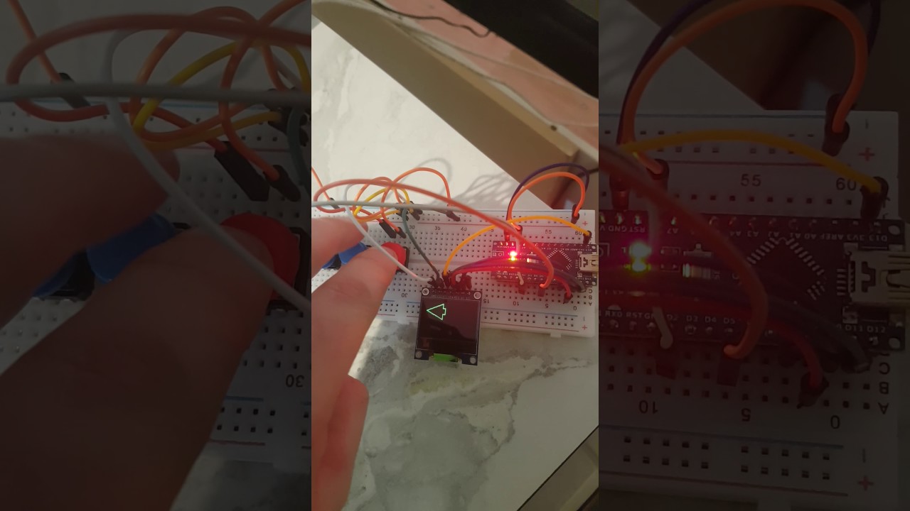
SUCCESSSSSSS!!!!!

I ended up using the JAVA image to code program and that worked straight away :smiley:

Thanks so much for your help everyone :smiley:

One last question-

Why do you think my previous program was not working? (with the data in a seperate .c file)

the .c file was "added" to the sketch- but is that enough for it to be referenced?

Thanks again.

Did you go back and try the original program structure again after you solved the bitmap conversion problem?

What happens if you use the extern declaration but move the graphics.c file out of the directory- does it compile or not? (That might tell you if its being linked in or not).

This include - Arduino & C: put a function and global variable in external file - Stack Overflow covers your problem so you might find useful information in the links.

Hi there.

Thanks for the ideas.

Firstly- no- still no joy when i try it in an external file- the screen displays that same old garbled mess.

I can however see that the .c file IS being referenced however because If i change the name within

#include <avr/pgmspace.h>

const unsigned char arrow []PROGMEM ={

from arrow to arro3 (for example) I get an error

exit status 1
Error compiling for board Arduino Nano.

Regardless--- atleast it works with the image data in the main program- Its messy but it works (and thats really what i care about)

My next problem is much harder... this coding is hard work on the noggin.

// constants won't change. Used here to set a pin number :
const int ledPin =  LED_BUILTIN;// the number of the LED pin

// Variables will change :
int ledState = LOW;             // ledState used to set the LED

// Generally, you should use "unsigned long" for variables that hold time
// The value will quickly become too large for an int to store
unsigned long previousMillis = 0;        // will store last time LED was updated

// constants won't change :
const long interval = 1000;           // interval at which to blink (milliseconds)

void setup() {
  // set the digital pin as output:
  pinMode(ledPin, OUTPUT);
}

void loop() {
  // here is where you'd put code that needs to be running all the time.

  // check to see if it's time to blink the LED; that is, if the
  // difference between the current time and last time you blinked
  // the LED is bigger than the interval at which you want to
  // blink the LED.
  unsigned long currentMillis = millis();

  if (currentMillis - previousMillis >= interval) {
    // save the last time you blinked the LED
    previousMillis = currentMillis;

    // if the LED is off turn it on and vice-versa:
    if (ledState == LOW) {
      ledState = HIGH;
    } else {
      ledState = LOW;
    }

    // set the LED with the ledState of the variable:
    digitalWrite(ledPin, ledState);

This makes sense...

But how do you do this if you do not have a HIGH output to measure. How do you make it remember that it has done something once (like sent a signal to draw a picture on your oled)- and not to do that same thing again unless xx has happened first.

I hope thats not too vague.

You dont need to limit yourself to HIGH and LOW states- the status variable can be assigned any arbitrary value that you wish eg

const int BLANK=0;
const int ARROW=1;
const int CIRCLE=2;
const int CROSS=3;
int currentState=BLANK;

void setup()
{
 // do the needed
}

void loop() {


  if (currentState==BLANK and (something else happens)) {
     draw_circle();
     currentState=CIRCLE;
  }
  
  if (currentState==CIRCLE and (something else happens)) {
     draw_cross();
     currentState=CROSS;
  }

   //etc etc for all the possible state changes.
   // you might even need more than one status variable

}

Obviously "something else happens" isnt real code- replace it with logic for your application.

ARgh that makes a ton of sense, thanks so much!!

....Kinda makes sense.

I have trimmed a test program down to this.. it should be able to change the screen color with a button press.. what am i missing?...

Also, What does the number beside the const int COLOR= actually mean/do?

#define sclk 13
#define mosi 11
#define cs   10
#define rst  9
#define dc   8

#define  BLACK           0x0000
#define BLUE            0x001F
#define RED             0xF800
#define GREEN           0x07E0
#define YELLOW          0xFFE0


#include <Adafruit_GFX.h>
#include <Adafruit_SSD1351.h>
#include <SPI.h>


Adafruit_SSD1351 display = Adafruit_SSD1351(cs, dc, rst);


const int hazardbuttonpin = 4;
const int rightbuttonpin = 3;
const int leftbuttonpin = 2;
const int batbuttonpin = 5;
const int llavail = 6;
const int llon = 7;


const int BLACK1=0;
const int RED1=1;
const int BLUE1=2;
const int YELLOW1=3;


int buttonState1 = 0;
int buttonState2 = 0;
int buttonState3 = 0;
int buttonState4 = 0;
int buttonState5 = 0;
int buttonState6 = 0;


void setup()
{

  display.begin();

  pinMode(hazardbuttonpin, INPUT_PULLUP);
  pinMode(rightbuttonpin, INPUT_PULLUP);
  pinMode(leftbuttonpin, INPUT_PULLUP);
  pinMode(batbuttonpin, INPUT_PULLUP);
  pinMode(llavail, INPUT_PULLUP);
  pinMode(llon, INPUT_PULLUP);
  
 display.fillScreen(BLACK);
currentState=BLACK1;

}

void loop() {
  
  
  if (currentState==BLACK1 and (buttonState3 == LOW)) {
     display.fillScreen(RED);
     currentState=RED1;
  }

  if (currentState==RED1 and (buttonState3 == LOW)) {
     display.fillScreen(YELLOW);
     currentState=YELLOW1;

}

  if (currentState==YELLOW1 and (buttonState4 == LOW)) {
     display.fillScreen(BLACK);
     currentState=BLACK1;

  }
}

PS. This total number of posts limit is a #@!%!%!.. why does it affect editing posts? :cry:

You have created variables such as buttonState3. You are looking at those variables to see if they change.

But you never change them! How does it know that buttonState3 should be linked to a particular digital input pin? It doesn't until you tell it. You have to write the code which reads the pin and saves the value in that variable.

Note that any time you use numbers in your variable names, you're doing it wrong. Give them real names like buttonStateLeft.

  buttonStateLeft = digitalRead(leftbuttonpin);

const int isnt really all that different to #define in this case- there is some debate as to which is best (see programming - Is it better to use #define or const int for constants? - Arduino Stack Exchange if you are interested) . All they do is make the program more readable..

One other issue you may encounter is switch bounce- a mechanical switch may open and close several times during a single button press and your program may be confused by the multiple events.

Thanks guys.

I find this extremely frustrating- definitely out of my depth.

Morgan S, thanks again.

I'm not at my home PC with the stuff right now however for some reason i thought the following was linking the buttons to the pins:

const int hazardbuttonpin = 4;
const int rightbuttonpin = 3;
const int leftbuttonpin = 2;
const int batbuttonpin = 5;
const int llavail = 6;
const int llon = 7;

I think i have tried doing too much too soon, now im flat out confused.

Those are just numbers, not pins. You must use digitalRead() or analogRead() to get a value from a pin.

Thanks again MorganS.

It seems i had accidentally deleted some fairly crucial bits.