I built a temperature data logger that was running successfully on a MEGA2560 and an Adafruit Data Logger Shield, RevC. I’m trying to migrate to use of an UNO R4 Wifi. In the future I’ll explore use of the internal RTC and possibly a FRAM module for logging data, but for now, it would be convenient if the old shield worked on an R4.
Connecting the shield seems to disable the 5V I2C bus on the R4. An I2C scanner cannot see any I2C devices when the shield is installed.
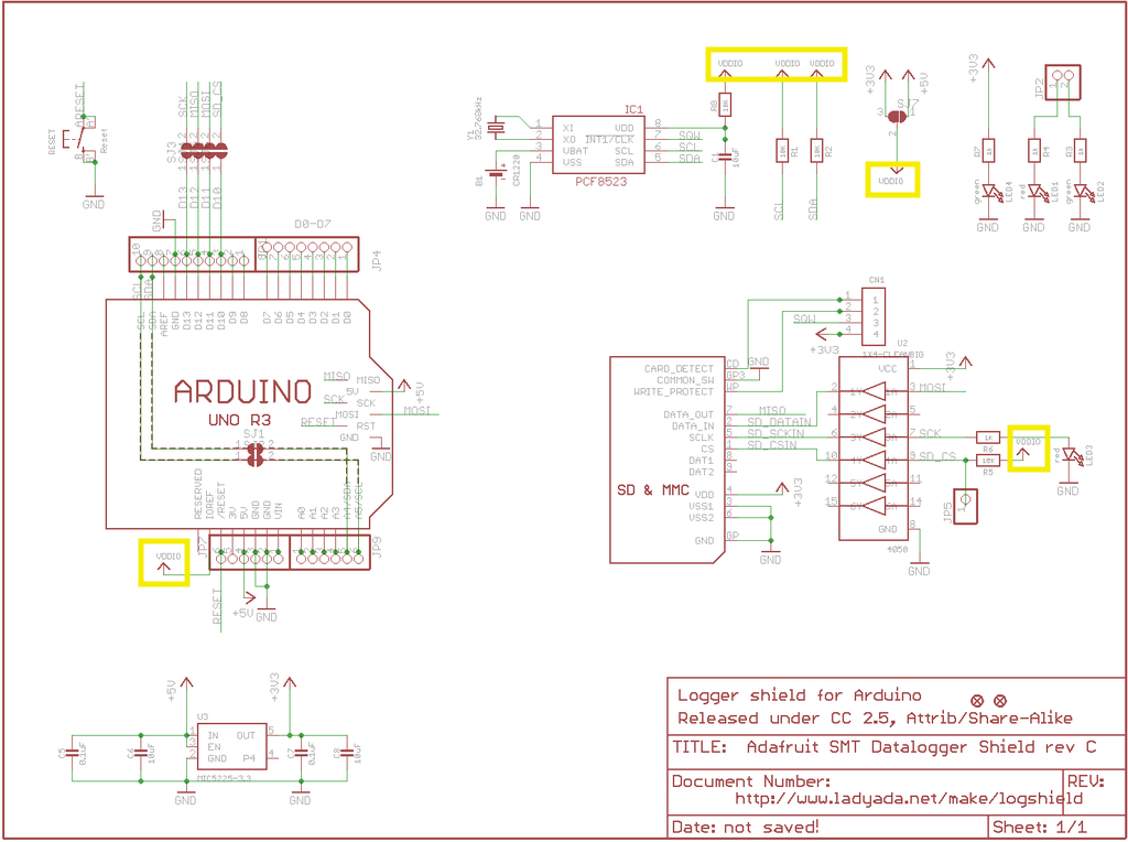
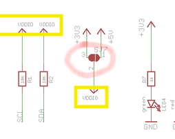
Looking at the shield circuit diagram, VDDIO is supplied by the Arduino IOREF pin, which is 5V on the UNO R3 and R4. The jumpers labeled SJ7 between VDDIO and 3V3 or 5V are both open on the shield. R1 and R2 are 10K pull ups on SCL and SDA. However, with the shield not attached to an Arduino, I measure 2.2 K ohm between the VDDIO pad of SJ7 and SCL/SDA. So, it appears the “as-built” R1 and R2 are 2.2K.
I don’t see anything obvious that would interfere with I2C communication. SCL and SDA are only connected to the RTC on the shield. I2C is fine when shield is on an UNO R3 or Mega. Is there something inherent to the R4 that is causing the problem?
Vddio is connected to 5V on the R4.
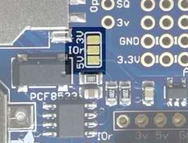
Looks to me like you've also got Vddio connected to 3.3V on your shield. Your jumpers may be open, but check your PCB. That looks like it's connected to me.
I agree it looks that way on the circuit drawing, but on the board, the pads are not connected.
I tried an experiment. Instead of plugging the entire shield into the R4, I only connected 4 pins: IOref, GND, SCL, and SDA. The R4 is able to use the external RTC! So the conflict/interference is coming from some other pin(s).
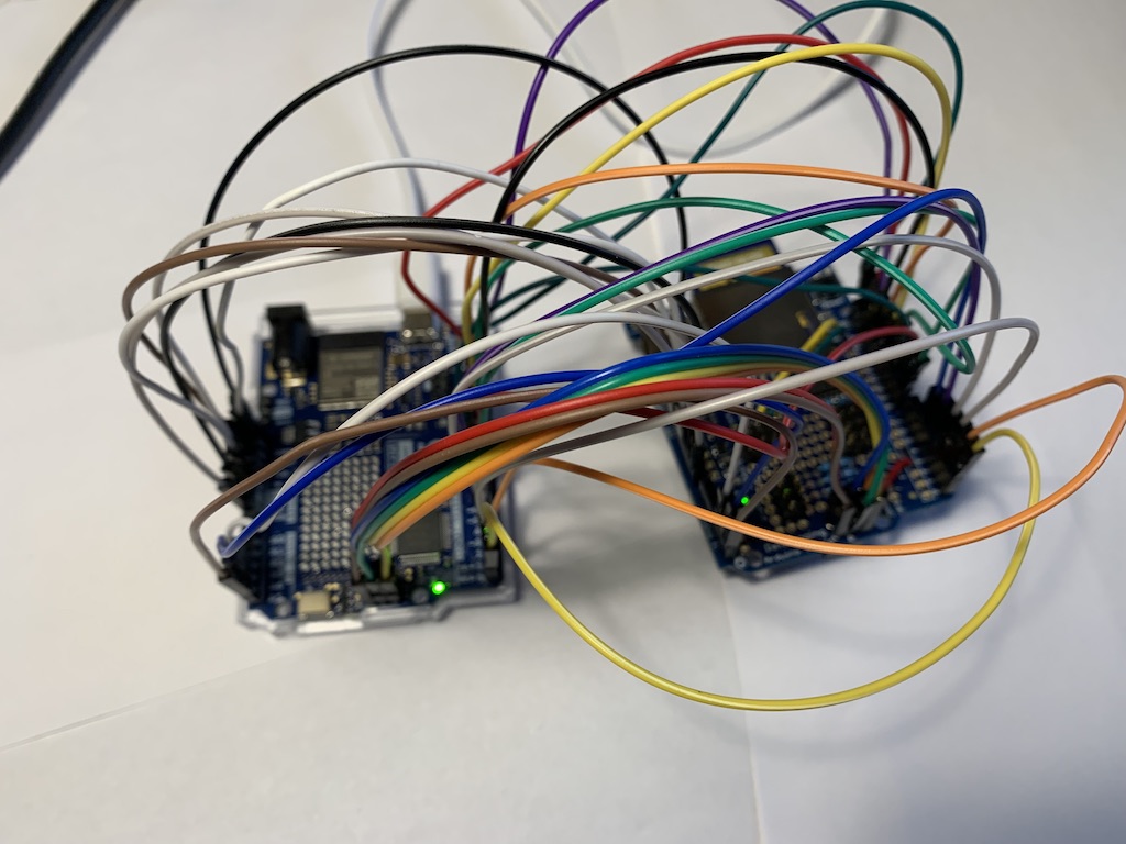
Connected MISO, 5V, SCK, and MOSI through ICSP header and Pin 10. RTC still works and SD card is working. I continued to connect pins to see what the conflict was, but the RTC kept working! It is as if the UNO R4 is claustrophobic. If the shield is connected via jumper cables, the shield works, but if it is close to the R4 it doesn’t work. I thought the shield might be touching the ESP header pins and shorting them somehow. When the shield is mounted, it doesn’t touch the ESP header pins, but when I pulled up on the shield, so it wasn’t fully seated, the RTC and SD card work! Can anyone tell me how having the shield fully seated is a problem?
Adafruit says the problem might be intermittent connection due to skinny stacking header pins. I bought the stacking headers from them. Apparently, the “good ones” have 0.025” square pins. The pins I’m having trouble with are 0.015” thick by 0.025” wide. I read that some people tin the pins to get a better connection if they get stuck with skinny pins.
Hi @quotidiano.
I think that is a reasonable hypothesis. I know exactly the sort of headers you are using, as I was unfortunate enough to obtain some myself, and they are indeed flimsy!
However, I would suggest you do a careful visual examination of your solder joints on the shield. It is possible the problem is caused by a low quality joint. This could result in there being an intermittent electrical continuity between the shield and the pin, which could be influenced by the pressures exerted on the solder joint depending on how far the shield is inserted into the UNO R4 WiFi.
You should see a smooth transition between the solder and the pad on the shield, and between the solder and the header pin:
📷
Solder Joint en.svg by SLUB Dresden / Carsten Pietzsch - CC BY-SA 4.0
Great suggestion. Some of my solder joints were marginal, but touching them up didn’t solve the problem. Tinning the SCL and SDA pins seems to make I2C communication with the RTC more reliable. The good news is that the shield is compatible with R4
1 Like
