Hello I bought the module Datalogger Recorder Shield and would like to connect it to an Mega 2560 board. Who can help me with hints on how to connect which pin of the data logger to the pins on the Mega 2560. I would also be happy to receive a small example program to test the connection and functionality.
Welcome to the forum
Please post a link to the shield that you have bought
If it is really a shield then it should plug directly into the appropriate Arduino board
Hello josbra
Welcome to the world's best Arduino forum ever.
This is a nice project to get started.
Keep it simple and stupid firstly.
Follow the example code that comes with the library or
run some tutorials for the hardware selected.
If you are happy with the results of the tutorials you can merge these to your project.
Have a nice day and enjoy coding in C++.
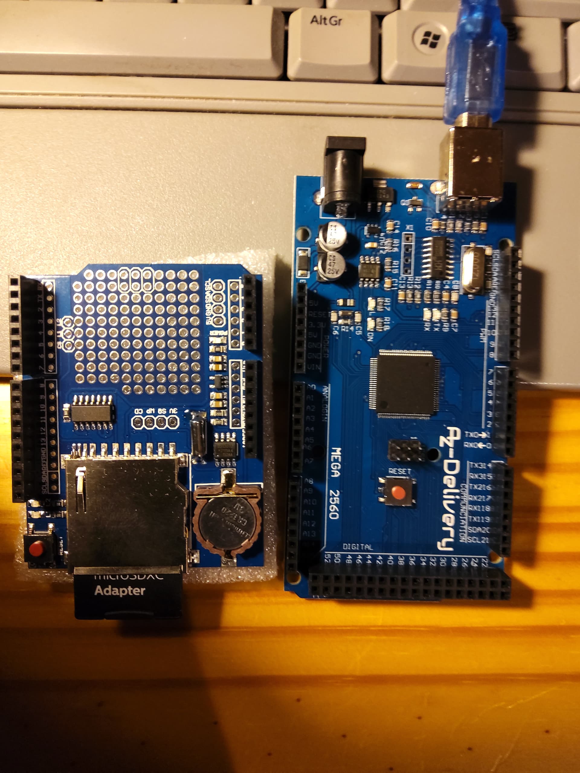
Thanks for your quick reply. See the attached image of the shield and the Mega 2560 board. In fact I could plug both boards directly. But the data logger was originally designed for the Arduino UNO and the UNO is differently wired as the Mega board and this I would like to do the wiring with cables (if possible).
What sort of interface does the shield use to communicate with the Arduino ?
Please post a link to the shield as previously requested
If the data logger shield is a clone of the Adafruit board, which is designed for an UNO, then the SPI signals don't appear on the same pins on a MEGA2560 as the do on the UNO.
Now, you may be able to salvage the situation, either by using a software SPI implementation on the MEGA, or with a wee bit of soldering - depending on your soldering skill, of course.
This is off the top of my head, so you should check the following for yourself:
If you can get a 2x3-pin female header (or 2 1x3-pin headers) I think that you can fit it/them to the underside of the data logger board where it shows the pads for the ICSP connector (at the top of the board in your picture in post #4). That should then connect into the ICSP pins on the MEGA2560 board where you can pick up the MOSI, MISO and SCK signals. Note that you could cut the tracks to the pins D11, D12 and D13 on the datalogger board just so there is no conflict, but if you don't use them, I believe they default to inputs on the MEGA2560.
Hopefully one of the other forum members can verify this, as, like I said, it's off the top of my head, and relies on you having some soldering skills.
Thank you all for your quick help and support.
I meanwhile found an article which describes how to resolve the issue.
Here is the link to it
It is in German but I guess that all of you who are interested can translate it with Google or other tools into English or another language.
I would check out where the pads for the 6-pin ICSP header go (if anywhere) on your shield. If they are connected to the card holder socket via the level translator IC, then you can use the hardware SPI interface, which is much faster than a software SPI library.
The Adafruit design also uses the ICSP header for the SPI signals. If your board is a clone, then simply fitting a 2x3 female header will get you the SPI connections you need.
Adafruit have a tutorial that tells you how to connect their datalogger boards to various types of Arduino including the Mega 2560.
It covers both their current version with ICSP header and an earlier version without.
https://learn.adafruit.com/adafruit-data-logger-shield
That should tell you what you need to know.
Great thanks. I will check this next week.
This topic was automatically closed 180 days after the last reply. New replies are no longer allowed.