DC motor control NEED ADVICE

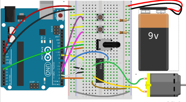
For a project I am doing, I have created a simple code using two push buttons and a potentiometer to control a DC motor, I wired the DC motor to an H-bridge and I know FOR SURE that my wiring is not the problem because I am using the same exact wiring diagram from project 10 of the Arduino uno start kit. My code should be very easy to use. Once uploaded, I should be able to hit "upPin" to turn the motor on in one direction for 3.5 seconds and when I hit the "downPin" it should go in the other direction for another 3.5 seconds. However, when I plug in the uno and upload the sketch, the loop IMMEDIATELY starts to run and doesn't wait for my pins, even though I set them up initially to LOW in the setup(). I have showed my professor, and he stated that my brackets were not in the correct spots for my IF statements. But when I move my IF brackets around any further, the motor doesn't run at all. He then suggested it has to do with the pins of the H-bridge but the circuit works perfectly fine for project 10 under FILES->EXAMPLES->STARTER KIT-> PROJECT TEN ZOETROPE so the way I am manipulating the pins in my own sketch shouldn't be what is causing my push buttons to not work. I just need help with understanding why my buttons are not being acknowledged and what I could do about it. The only reason I put the five second delays is because the motor will just keep running and keep switching directions if I didn't add some kind of pause in between the two.
Here is my code:

const int pin1 = 2; // to pin 7 on IC which is motor logic pin for terminal 2
const int pin2 = 3; // to pin 2 on IC, where current flows through the load
const int ePin = 9; // to pin 1 on IC, enables pin on H-bridge to control motor
const int downPin = 4; // switch to change direction downward
const int upPin = 5; // switch to start motor upward
const int potPin = A0; // potentiometer
int switchStateUp = 0; // state to move upward
int switchStateDown = 0; // state to go down or reverse direction
int motorEnabled = 0; // Turns the motor on/off
int motorSpeed = 0; // speed of the motor

void setup() {
  // put your setup code here, to run once:
  pinMode(downPin, INPUT);
  pinMode(upPin, INPUT);
  pinMode(pin1, OUTPUT);
  pinMode(pin2, OUTPUT);
  pinMode(ePin, OUTPUT);

  digitalWrite(ePin, LOW);
  digitalWrite(upPin, LOW);
  digitalWrite(downPin, LOW);
}

void loop() {
  switchStateUp = digitalRead(upPin);
  motorSpeed = analogRead(potPin) / 4 ;
  analogWrite(ePin, motorSpeed);
  if (upPin == HIGH);
  {
    digitalWrite(ePin, HIGH);
  }
  digitalWrite(pin1, HIGH);
  digitalWrite(pin2, LOW);

  delay(3500);
  if (upPin == LOW);
  digitalWrite(pin1, LOW);
  digitalWrite(pin2, LOW);
  digitalWrite(ePin, LOW);
  motorEnabled = digitalRead(ePin) ;

  delay(5000);

  switchStateDown = digitalRead(downPin);
  if (downPin == HIGH) ;
  {
    digitalWrite(ePin, HIGH);
  }
  digitalWrite(pin1, LOW);
  digitalWrite(pin2, HIGH);

  delay(3500);
  if (downPin == LOW);
  digitalWrite(pin1, LOW);
  digitalWrite(pin2, LOW);
  digitalWrite(ePin, LOW);
  motorEnabled = digitalRead(ePin) ;


  delay(5000);
}

Always show us a good schematic of your proposed circuit.
Show us a good image of your ‘actual’ wiring.
Give links to components.

Avoid delay( ) as if it was a plague.


if (upPin == HIGH);
And
if (upPin == LOW);

Is not doing what you think it does.

Hint upPin = 5 :wink:

const int upPin = 5; // switch to start motor upward

if (downPin == HIGH) ;

Same problem :woozy_face: .

FYI

I have removed the if (up/downPin== LOW)
and it is still not acknowledging my buttons

const int pin1 = 2; // to pin 7 on IC which is motor logic pin for terminal 2
const int pin2 = 3; // to pin 2 on IC, where current flows through the load
const int ePin = 9; // to pin 1 on IC, enables pin on H-bridge to control motor
const int downPin = 4; // switch to change direction downward
const int upPin = 5; // switch to start motor upward
const int potPin = A0; // potentiometer   
int switchStateUp= 0; // state to move upward
int switchStateDown = 0; // state to go down or reverse direction
int motorEnabled = 0; // Turns the motor on/off
int motorSpeed = 0; // speed of the motor

void setup() {
  // put your setup code here, to run once:
  pinMode(downPin, INPUT);
  pinMode(upPin, INPUT);
  pinMode(pin1, OUTPUT);
  pinMode(pin2, OUTPUT);
  pinMode(ePin, OUTPUT);
  
 digitalWrite(ePin, LOW);
 digitalWrite(upPin, LOW);
 digitalWrite(downPin, LOW);
}

void loop() {
switchStateUp = digitalRead(upPin);
motorSpeed = analogRead(potPin) / 4 ;
analogWrite(ePin, motorSpeed);
if (upPin == HIGH);
{ digitalWrite(ePin, HIGH); }
digitalWrite(pin1, HIGH);
digitalWrite(pin2, LOW);
  
delay(1500);

digitalWrite(ePin, LOW);

delay(3000);

switchStateDown = digitalRead(downPin);
if (downPin == HIGH) ;
{ digitalWrite(ePin, HIGH); }
digitalWrite(pin1, LOW);
digitalWrite(pin2, HIGH);

delay(1500);

digitalWrite(ePin, LOW);

delay(3000);
}

image

This is the wiring diagram I am using

You have:

And


What you need is:

if (switchStateUp == HIGH); or LOW

AND

if (switchStateDown == HIGH) ; or LOW


Get rid of the delay( ) lines.


A 9v battery is a very poor choice as it has little capacity.

I am following your advice very carefully, but my buttons are still not being acknowledged and the loop immediately begins to run as soon as it is uploaded. So if I take away the delays, the motor will not switch directions because it follows the first set of directions in one state.

const int pin1 = 2; // to pin 7 on IC which is motor logic pin for terminal 2
const int pin2 = 3; // to pin 2 on IC, where current flows through the load
const int ePin = 9; // to pin 1 on IC, enables pin on H-bridge to control motor
const int downPin = 4; // switch to change direction downward
const int upPin = 5; // switch to start motor upward
const int potPin = A0; // potentiometer   
int switchStateUp= 0; // state to move upward
int switchStateDown = 0; // state to go down or reverse direction
int motorEnabled = 0; // Turns the motor on/off
int motorSpeed = 0; // speed of the motor

void setup() {
  // put your setup code here, to run once:
  pinMode(downPin, INPUT);
  pinMode(upPin, INPUT);
  pinMode(pin1, OUTPUT);
  pinMode(pin2, OUTPUT);
  pinMode(ePin, OUTPUT);
  
 digitalWrite(ePin, LOW);
 digitalWrite(upPin, LOW);
 digitalWrite(downPin, LOW);

}

void loop() {
switchStateUp = digitalRead(upPin);
motorSpeed = analogRead(potPin) / 4 ;
analogWrite(ePin, motorSpeed);
if (switchStateUp == HIGH);
{ digitalWrite(ePin, HIGH); 
digitalWrite(pin1, HIGH);
digitalWrite(pin2, LOW); }
  
delay(1500);

digitalWrite(ePin, LOW);

delay(3000);

switchStateDown = digitalRead(downPin);
if (switchStateDown == HIGH) ;
{ digitalWrite(ePin, HIGH); 
digitalWrite(pin1, LOW);
digitalWrite(pin2, HIGH); }

delay(1500);

digitalWrite(ePin, LOW);

delay(3000);
}

I will try to attach a video real quick so you can see.

Don’t follow instructions unless you understand the instructions.

You can place some Serial.println(“message”); at strategic places to prove variables are what you think they are.

Can you please explain?

Hi,
Sorry but had to psread it out into point from to make it easier to read.

Tom.. :smiley: :+1: :coffee: :australia:

Hi,
Do you have a DMM?
Can you check at the UNO input pins, that pressing the buttons makes the input pin go to 5V and to 0V when released?

Can you please post a copy of your circuit, in CAD or a picture of a hand drawn circuit in jpg, png?
Hand drawn and photographed is perfectly acceptable.
Please include ALL hardware, component names and pin labels.

The Fritzy does not tell us what the pins are on the motor driver IC.

Thanks.. Tom.. :smiley: :+1: :coffee: :australia:

I do not have one with me at this moment. However, when I upload the project 10 from the starter kit, it functions properly and this wiring diagram is for project ten of the arduino uno starter kit. So the push buttons do what they should with this sketch:

const int controlPin1 = 2; // connected to pin 7 on the H-bridge
const int controlPin2 = 3; // connected to pin 2 on the H-bridge
const int enablePin = 9;   // connected to pin 1 on the H-bridge
const int directionSwitchPin = 4;  // connected to the switch for direction
const int onOffSwitchStateSwitchPin = 5; // connected to the switch for turning the motor on and off
const int potPin = A0;  // connected to the potentiometer's output

// create some variables to hold values from your inputs
int onOffSwitchState = 0;  // current state of the on/off switch
int previousOnOffSwitchState = 0; // previous position of the on/off switch
int directionSwitchState = 0;  // current state of the direction switch
int previousDirectionSwitchState = 0;  // previous state of the direction switch

int motorEnabled = 0; // Turns the motor on/off
int motorSpeed = 0; // speed of the motor
int motorDirection = 1; // current direction of the motor

void setup() {
  // initialize the inputs and outputs
  pinMode(directionSwitchPin, INPUT);
  pinMode(onOffSwitchStateSwitchPin, INPUT);
  pinMode(controlPin1, OUTPUT);
  pinMode(controlPin2, OUTPUT);
  pinMode(enablePin, OUTPUT);

  // pull the enable pin LOW to start
  digitalWrite(enablePin, LOW);
}

void loop() {
  // read the value of the on/off switch
  onOffSwitchState = digitalRead(onOffSwitchStateSwitchPin);
  delay(1);

  // read the value of the direction switch
  directionSwitchState = digitalRead(directionSwitchPin);

  // read the value of the pot and divide by 4 to get a value that can be
  // used for PWM
  motorSpeed = analogRead(potPin) / 4;

  // if the on/off button changed state since the last loop()
  if (onOffSwitchState != previousOnOffSwitchState) {
    // change the value of motorEnabled if pressed
    if (onOffSwitchState == HIGH) {
      motorEnabled = !motorEnabled;
    }
  }

  // if the direction button changed state since the last loop()
  if (directionSwitchState != previousDirectionSwitchState) {
    // change the value of motorDirection if pressed
    if (directionSwitchState == HIGH) {
      motorDirection = !motorDirection;
    }
  }

  // change the direction the motor spins by talking to the control pins
  // on the H-Bridge
  if (motorDirection == 1) {
    digitalWrite(controlPin1, HIGH);
    digitalWrite(controlPin2, LOW);
  } else {
    digitalWrite(controlPin1, LOW);
    digitalWrite(controlPin2, HIGH);
  }

  // if the motor is supposed to be on
  if (motorEnabled == 1) {
    // PWM the enable pin to vary the speed
    analogWrite(enablePin, motorSpeed);
  } else { // if the motor is not supposed to be on
    //turn the motor off
    analogWrite(enablePin, 0);
  }
  // save the current on/off switch state as the previous
  previousDirectionSwitchState = directionSwitchState;
  // save the current switch state as the previous
  previousOnOffSwitchState = onOffSwitchState;
}

but the pins are not being acknowledged with my sketch:

const int pin1 = 2; // to pin 7 on IC which is motor logic pin for terminal 2
const int pin2 = 3; // to pin 2 on IC, where current flows through the load
const int ePin = 9; // to pin 1 on IC, enables pin on H-bridge to control motor
const int downPin = 4; // switch to change direction downward
const int upPin = 5; // switch to start motor upward
const int potPin = A0; // potentiometer   
int switchStateUp= 0; // state to move upward
int switchStateDown = 0; // state to go down or reverse direction
int motorEnabled = 0; // Turns the motor on/off
int motorSpeed = 0; // speed of the motor

void setup() {
  // put your setup code here, to run once:
  pinMode(downPin, INPUT);
  pinMode(upPin, INPUT);
  pinMode(pin1, OUTPUT);
  pinMode(pin2, OUTPUT);
  pinMode(ePin, OUTPUT);
  
 digitalWrite(ePin, LOW);
 digitalWrite(upPin, LOW);
 digitalWrite(downPin, LOW);

}

void loop() {
switchStateUp = digitalRead(upPin);
motorSpeed = analogRead(potPin) / 4 ;
analogWrite(ePin, motorSpeed);
if (switchStateUp == HIGH);
{ digitalWrite(ePin, HIGH); 
digitalWrite(pin1, HIGH);
digitalWrite(pin2, LOW); }
  
delay(1500);

digitalWrite(ePin, LOW);

delay(3000);

switchStateDown = digitalRead(downPin);
if (switchStateDown == HIGH) ;
{ digitalWrite(ePin, HIGH); 
digitalWrite(pin1, LOW);
digitalWrite(pin2, HIGH); }

delay(1500);

digitalWrite(ePin, LOW);

delay(3000);
}

I understand you might be annoyed with my lack of knowledge on microcontrollers, but I appreciate all the help you have provided me with!

You are wrong, not annoyed at all.

Ask questions if you do not fully understand what is being conveyed.

  • If you are willing, we can take this one step at a time so you will fully understand the what and why things are done as they are.

  • Are you willing to put some time into this ?

Yes, very much so.

Okay

Run this sketch as is.

Open the serial monitor and set the baud rate to 9600.

  • What do you see when the up/down switches are pressed ?

  • What do you see happening on the built in LED pin 13 ?

//
//  Version   YY/MM/DD      Comments
//  =======   ========      ========================================================
//  1.00      22/11/17      Running code
//
//


#define ENABLED             true
#define DISABLED            false

#define RelayOFF            HIGH
#define RelayON             LOW

#define PUSHED              HIGH
#define RELEASED            LOW

//********************************************^************************************************
const byte pin1           = 2;  //to pin 7 on IC which is motor logic pin for terminal 2
const byte pin2           = 3;  //to pin 2 on IC, where current flows through the load
const byte ePin           = 9;  //to pin 1 on IC, enables pin on H-bridge to control motor

const byte heartbeatLED   = 13;

const int downPin         = 4;  //switch to change direction downward
const int upPin           = 5;  //switch to start motor upward

const int potPin          = A0; //potentiometer

byte lastUpPin            = RELEASED;
byte lastDownPin       = RELEASED;


//TIMER stuff
unsigned long heartbeatMillis;
unsigned long checkSwitchesMillis;

//                                       s e t u p ( )
//********************************************^************************************************
void setup()
{
  Serial.begin(9600);

  pinMode(downPin, INPUT);
  pinMode(upPin, INPUT);

  pinMode(heartbeatLED, OUTPUT);

  pinMode(pin1, OUTPUT);
  pinMode(pin2, OUTPUT);
  pinMode(ePin, OUTPUT);

  digitalWrite(pin1, LOW);
  digitalWrite(pin2, LOW);
  digitalWrite(ePin, LOW);

} //END of   setup()


//                                        l o o p ( )
//********************************************^************************************************
void loop()
{
  //*********************************                         heartbeat TIMER
  //is it time to toggle the heartbeatLED (every 500ms)?
  if (millis() - heartbeatMillis >= 500ul)
  {
    //restart this TIMER
    heartbeatMillis = millis();

    //toggle the heartbeatLED
    digitalWrite(heartbeatLED, !digitalRead(heartbeatLED));
  }

  //*********************************                         checkSwitches TIMER
  //is time to check our switches ?
  if (millis() - checkSwitchesMillis >= 50ul)
  {
    //restart this TIMER
    checkSwitchesMillis = millis();

    checkSwitches();
  }


  //*********************************
  //other non blocking code goes here
  //*********************************

} //END of    loop()


//                               c h e c k S w i t c h e s ( )
//********************************************^************************************************
void checkSwitches()
{
  byte currentState;

  //*********************************                         upPin
  currentState = digitalRead(upPin);

  //did this switch change state ?
  if (lastUpPin != currentState)
  {
    //update to the new state
    lastUpPin = currentState;

    //is the switch now pushed ?
    if (currentState == PUSHED)
    {
      Serial.println("upPin is closed");
    }

  } //END of this switch

  //*********************************                         downPin
  currentState = digitalRead(downPin);

  //did this switch change state ?
  if (lastDownPin != currentState)
  {
    //update to the new state
    lastDownPin = currentState;

    //is the switch now pushed ?
    if (currentState == PUSHED)
    {
      Serial.println("downPin is closed");
    }

  } //END of this switch

} //END of   checkSwitches()

//********************************************^************************************************
1 Like

Hi,

You need to do some troubleshooting using the IDE monitor and Serial.println statements to display your variables.

Tom... :smiley: :+1: :coffee: :australia:

1 Like

What my serial monitor is telling me when pressing my switches:
upPin is closed
downPin is closed
upPin is closed
downPin is closed
upPin is closed

LED is constantly blinking.

Do you understand what is happening in the sketch ?

Is the left side of the schematic here what you are trying to copy ?

2022-11-17_18-33-04