I want to control a brushed dc motors using two mosfets to trigger forward and reverse circuity.
is there anything else I need to adjust?
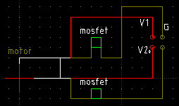
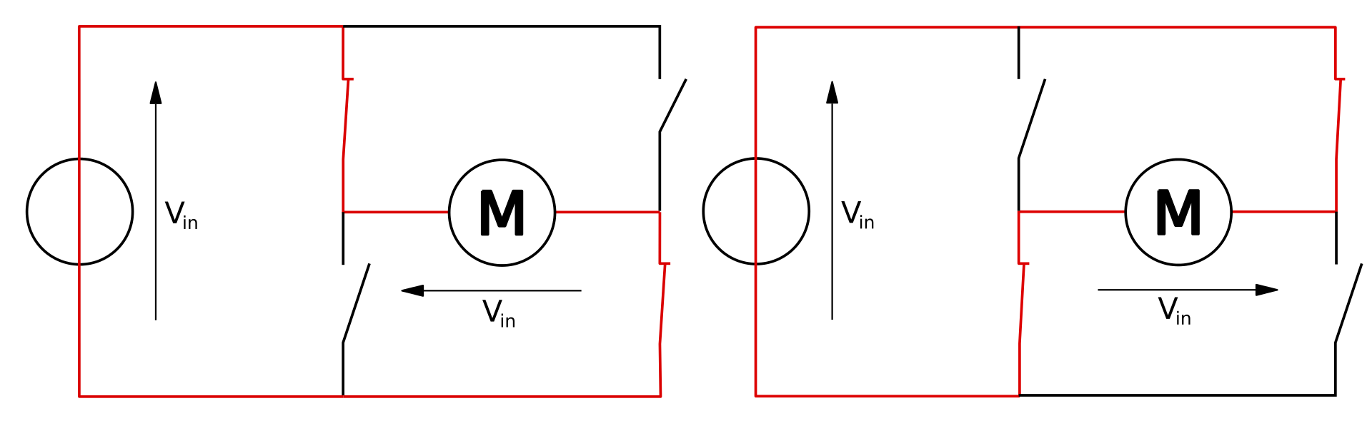
Original Circuit diagram
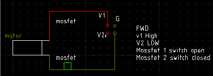
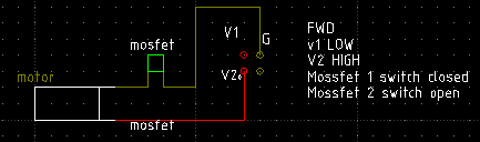
Example to drive REVERSE,
FORWARD
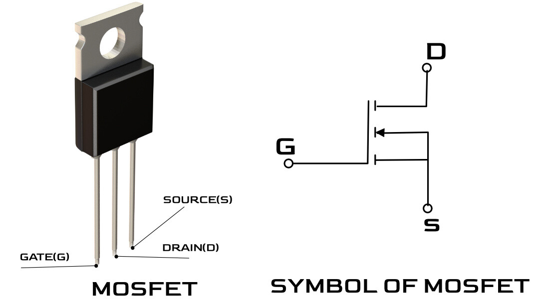
Your MOSFET has only 2 pins?
1 Like
awneil
September 18, 2023, 9:15pm
3
I don't get what you're trying to show in your diagrams.
What are V1, V2 and G, and what makes them "high" or "low"?
Before worrying about MOSFETs, perhaps just draw with normal open/closed switches?
You would normally use four - in a so-called "H-bridge".
An H-bridge is an electronic circuit that switches the polarity of a voltage applied to a load. These circuits are often used in robotics and other applications to allow DC motors to run forwards or backwards. The name is derived from its common schematic diagram representation, with four switching elements configured as the branches of a letter "H" and the load connected as the cross-bar.
Most DC-to-AC converters (power inverters),
most AC/AC converters,
the DC-to-DC push–pull converter, isola...
The four switches (which could be MOSFETs) allow the motor to go either forwards or backwards:
DVDdoug
September 18, 2023, 9:18pm
4
For forward and reverse you actually need 4 MOSFETs in a bridge configuration
It's not unusual for people to build a unidirectional motor driver with one MOSFET but for bi-directional control, most people buy a bridge driver chip or a board assembly.
1 Like
See DVDdoug's reply.
1 Like
system
March 16, 2024, 9:24pm
6
This topic was automatically closed 180 days after the last reply. New replies are no longer allowed.