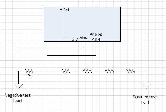
Okay, I am trying to get the Uno to monitor DC voltage, and for now display current, min/max on the LCD screen. All resistors are 220 ohm. I am expecting 12 volt max and am using the Uno's 3 volt as a reference. I have measured the actual resistance across the test leads as 522 ohms and across R1 as 522 ohms. The variable ResistorRatio was calculated using the measured resistances. Using a multimeter, I checked a 9 volt battery (9.9 volts) and a AA (1.4 volts). Using the code below I read AA = 1.44 and 9v = 6.37. Any Idea what I am missing? Oh and I tried it both with and without a 10 microfarad cap across R1. No difference.
Your fault does look rather close to what I'd expect if your ADC were referenced to 5V not 3.3
Perhaps check the line
analogReference(EXTERNAL); //set to the Arduino 3.3 volt
By the way, I've had ok performance doing something similar with a zener near to the battery + as well as a potential divider.
Doing that can double the resolution of ad steps for you, at the expense of restricting valid input to the top half of the range.
Also, mine works with considerably larger resistance values, for example 10kOhm and 39kOhm on an arduino 168.
Dang it, I forgot to add that. I guess that might help lol
Okay, how do I add an image. I hit the image button and it just gives me tags. I don't know how to get the image in there.
without resistors, it would be just the battery. aa= 1.4, 9v = 1.9.
Did you mean 9.9 rather than 1.9?
With the voltage divider (the five resistors in your diagram) in place, can you try measuring the voltage at the analog input pin with your multimeter. You would be expecting 1.4 / 5 and 9.9 / 5, I guess.
I think I just figured it out. I think the batteries are low. When I tested the 9 volt across the full resister value it measured 6.5. Does that sound like a good reason why a 9 volt would measure 9.9 with no load, but 6.5 with about 1k ohm load?
What type of battery will be the one you use in the actual system, the 12V one? You could follow up ad2049q's suggestion of using larger resistors to reduce the current drawn.
Good grief!!!! I fought with this thing for the whole morning! Sure enough. I tested on a wall wart PS and measured accurately. I am at work so somewhat limited to what I can test. Only batteries are old. UGH. Thanks for all your help and the really fast replies! What a team you are. I only hope I can help others as I get further along.
I don't think you understood my question. Your diagram shows resistors in series with meter leads. I asked you to measure the voltage at the analog input pin with a multimeter using normal leads without resistors. This means I want you to measure the arduino INPUT voltage using the exact circuit shown in your diagram , but with a meter with leads exactly the way they come out of the package , to compare the voltage you read on your serial monitor with the voltage of meter measuring at the exact same point the arduino is measuring to see if the arduino input voltage is LESS than the AREF VOLTAGE of 3.3V. So all you need to do is get a meter and measure the analog input pin voltage without changing the circuit, meaning without removing resistors. I would not have phrased my request that way if you had not drawn meter leads in your drawing. If we ignore that then I would just say,
"is the voltage you are reading on the serial port the same voltage you measure with a meter or is there a difference ?