Summary
When comparing measurements of a given constant voltage of 700mV between Arduino (via analogread ADC), scope, and DMM, then the values are nicely within approx 1% of each other. However, when measuring an (aprox) 700mV voltage drop over a shunt caused by a battery DC dead short, then the voltage measured by the scope is roughly 200mV higher than the Arduino. Apparently, the change from a static voltage to a dynamic one changed something. The Question: What could be the reason for this and how to possibly correct this? Note that the "Waveform" of the short circuit current (or corresponding shunt voltage) matches well between Arduino and scope.
Context
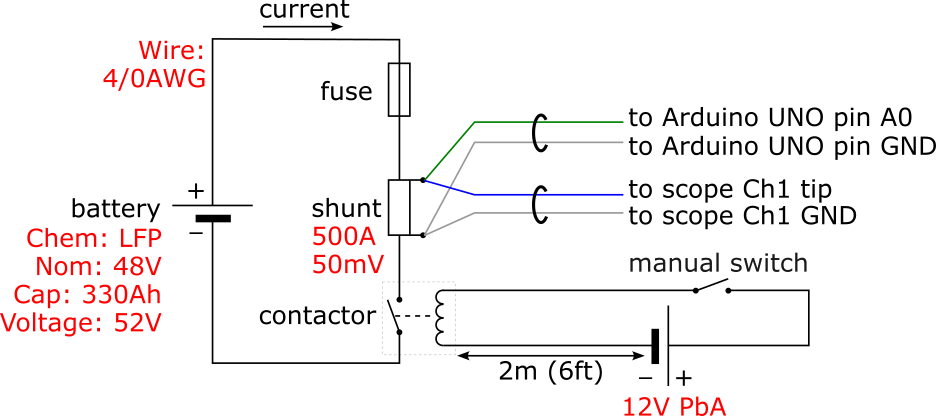
This project. Edit: based on comments below (limitations to link access), more context here: The goal is to measure the dead-short-circuit current and fuse clearing time with an LFP battery.


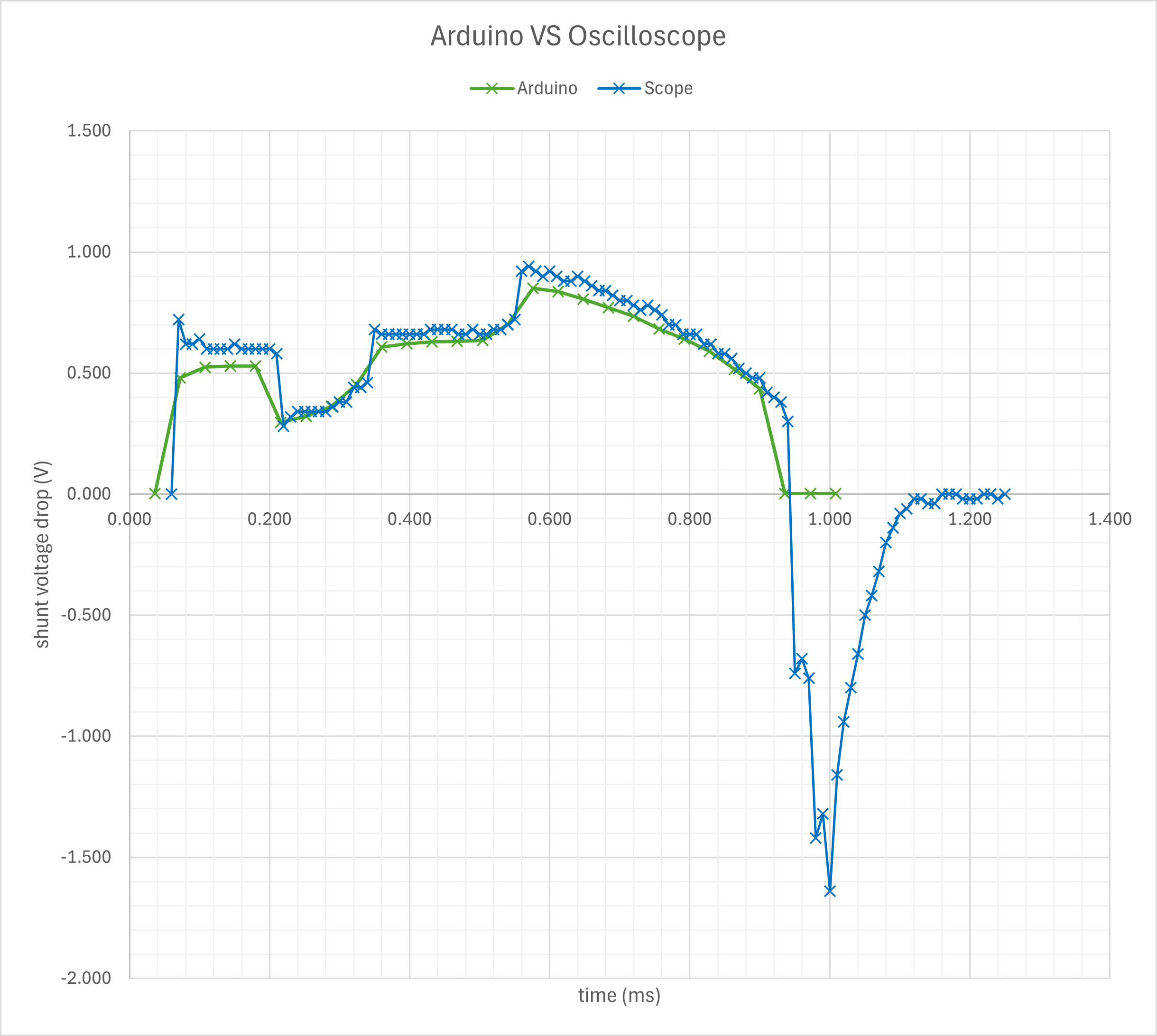
Graph notes: I manually horizontally shifted the two curves to align them. Also, 1V corresponds to 10kA.
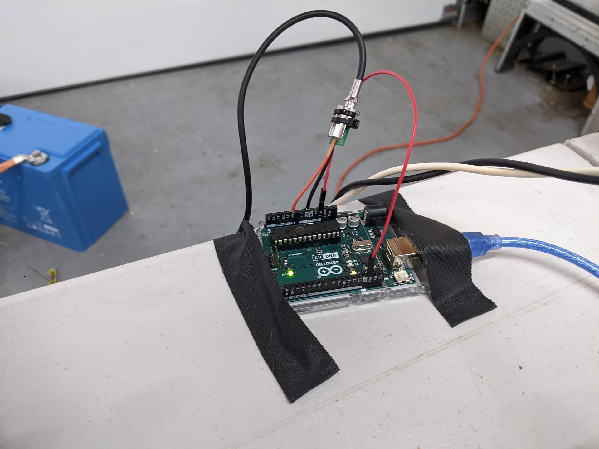
Hardware (with voltage accuracy):
- Shunt: 500A 50mV Victon SmartShunt; Made of Manganin | has enough thermal mass to withstand the short, trust me.
- Genuine Arduino UNO R3 with ATMEL ATMEGA328P. (ADC accuracy: 2 LSB); Calibrated reference voltage.
- Oscilloscope: Siglent SDS1202X (DC Gain Accuracy for 5mV/div to 10V/div: ≤ +/-3%; offset accuracy for ≥2 mV/div: +/- (1%·Offset + 1.5%·8·V/div + 2mV); warmed up 30min; brand new.
- DMM: Klein Tools CL380 (accuracy: 1% + 8 digits).
- Probes (used for both scope and arduino): Siglent PP215 probes. The probes for Arduino and scope hook up at the same points on the shunt.
Code
/*
Goal: Log the smartshunt current (using the voltage drop accross the shunt) during a DC dead short.
Event duration: Roughly a millisecond. The sampling interval should be at least an order smaller than that.
The code below uses "fast sampling" until the dynamic mem is full.
After that, "slow sampling" is done due to the time needed to transfer through serial to a PC USB port.
*/
const float vref = 3.304; // -- 3.304V (internal Arduino); the actual reference voltage may deviate a bit; See also: https://skillbank.co.uk/arduino/measure2.htm
const float voltageResolution = vref / 1024; // -- vref / 1024;
const float shuntSensitivity = 500.0 / 50e-3; // -- 500A / 50mV; shunt hardware specs
const int totNumSamples = 4096; // -- 4096; the chosen total number of samples
const int maxMemSamples = 350; // -- 350 seems to be the max, leaving ample dynamic memory for local variables and prevent unexpected behavior.
const int numCurrentDecimals = 0; // -- 0; The current resolution is >1A, so no decimals needed Zero decimals. Set to 3 for directly checking ADC voltage measurement accuracy.
float currentArr[maxMemSamples] = { 0 }; // -- max allowed array size is 32767 bytes / 4 bytes per float = 8191 floats, but due tot dynamic mem restrictions, really only 2048b / 4b = 512 floats.
int curSampleID = 0; // -- 0; current sample ID
int analogPinReading; // -- value ranging from 0 to 1023
float curCurrent; // -- The current current (Amperes) value .
bool triggered = false; // -- true once the voltage is above zero. Before triggering, no mem is wasted to store zero-valued samples.
bool memFull = false; // -- true once currentArr is full
bool finished = false; // -- true once all samples have been taken
unsigned long startTimeMicros = 0; // -- 0; start time, assigned final value when triggered (us)
unsigned long memFullTimeMicros; // -- time at which currentArr[] is full (us)

void setup()
{ // -- setup code to run once:
  analogReference(EXTERNAL); // -- EXTERNAL; Add jumper between internal 3.3V output pin and AREF pin. See also: https://www.arduino.cc/reference/en/language/functions/analog-io/analogreference/
  Serial.begin(1000000); // -- 1000000; default is 9600; use same value in Serial Monitor and/or Putty!

  // -- https://www.gammon.com.au/adc
  ADCSRA &= ~(bit (ADPS0) | bit (ADPS1) | bit (ADPS2)); // -- Clears prescaler bits.
  ADCSRA |= bit (ADPS2);                               //  16 -- use this one
}

void loop() { // -- main code, run infinitely:
  if (finished) return; // -- stops sampling
  analogPinReading = analogRead(A0); // -- accuracy: 2 LSB; see also https://arduino.stackexchange.com/questions/9384/uno-analog-input-voltage-reading-not-accurate

  if (!triggered && analogPinReading <= 8) // -- idle && "zero" current. If "&& analogPinReading == 0) would be used instead, then ADC inaccuracies immediately result in true. See also the measurement results: <= 7 is noise.
  { // -- Sitting idle *and* still zero current. Current has not yet started flowing. After current flow start, a zero-value current will not stop sampling.
    return;
  } // -- else: dead short current has started to flow
  if (!triggered)
  { // -- Sitting idle, *but* current just started to flow. The following code is executed only once:
    startTimeMicros = micros(); // -- Stores start time, and not any earlier, i.e. not in setup(), bc then the irrelevant pre-trigger idle time would be counted too.
    triggered = true; // -- Causes sampling to start.
  }

  curCurrent = (analogPinReading + 0.5) * voltageResolution * shuntSensitivity; // -- Units: bits x (bits/V) x (A/V) = A; See also https://skillbank.co.uk/arduino/measure2.htm
  if (!memFull) currentArr[curSampleID] = curCurrent;
  else Serial.println(String(micros()) + "\t" + String(curCurrent, numCurrentDecimals)); // -- mem is full

  if (curSampleID == maxMemSamples - 1)
  { // -- memory (or, actually, the *array*) is full:
    memFullTimeMicros = micros(); // -- Logs the memory full time before spending time exporting data.
    memFull = true; // -- Causes the next sample to be no longer stored in memory.
  }

  curSampleID++;

  if (curSampleID == totNumSamples) // -- Post-processing:
  { // -- All samples have been taken; the "slow samples" have already been transferred to serial.
    unsigned long finishTimeMicros = micros(); // -- stores the finish time
    delay(100); // -- Attempt to prevent random serial output.
    // -- Transfer samples from dynamic mem to USB and log how long that takes:
    for (int i = 0; i < maxMemSamples; i++) Serial.println("\t" + String(currentArr[i], numCurrentDecimals)); // -- The tab char is added here for consistency with "fast samples" and make import into Excel easier.
    Serial.println("Mem xfer time: " + String((micros() - finishTimeMicros) * 0.001, 0) + " ms."); // -- Formats float with 3 decimals.
    // -- Calculate and log the "slow sample" time interval (sent out first to serial):
    float slowIntervalMillis = (finishTimeMicros - memFullTimeMicros) / float(totNumSamples - maxMemSamples) * 0.001;
    Serial.println("Avg time interval (non-mem): " + String(slowIntervalMillis,3) + " ms."); // -- Formats float with 3 decimals
    // -- Calculate and log the "fast sample" time interval (sent out last to serial):
    float fastIntervalMillis = (memFullTimeMicros - startTimeMicros) / float(maxMemSamples - 1) * 0.001; // -- calculates avg interval between fast samples.
    Serial.println("Avg time interval (    mem): " + String(fastIntervalMillis, 3) + " ms."); // -- Formats float with 3 decimals
    // -- Calculate and log the total sampling time:
    Serial.println("Total sampling time: " + String((finishTimeMicros - startTimeMicros) * 0.001, 0) + " ms."); // -- formats float with 3 decimals.

    finished = true;
    return;
  }
}