I am working on a project to monitor an ignition coil of an antique car. The circuit monitors the current charging the ignition coil and measures when that current peaks and the coil fires. The essence of the circuit is a current monitor and a solid state relay to switch the coil on and off.
I have gotten the project to a state where it works fairly well but I am dealing with unreliability due to the electrical noise caused by having, what is essentially, a spark gap transmitter a few feet away. I would love some pointers on where I might start to make the circuit more stable against this interference. I know some of the basics of electronics but I'm still learning about how to deal with these more complicated issues.
I will attach a schematic below. I tried to represent the wiring routes and component positions as accurately as possible in case it is important. The main issue I experience is the uC resetting. When I check the reset cause register I get an external reset code despite not pressing the reset button obviously. Previously I had tried to wire a cable to the reset button which made it worse. Along the same line I tried using an ISR to trigger a reset via the WDT to implement a reset button but it would cause resets when the coil fired despite the button not being pressed. I also see the display flash when the coil fires which I assume is a symptom of some serious noise issues. It seems to my naive understand that for a reset to happen like this GND and RST pins would have to be moving close in voltage somehow?
The code is below, I don't think you need to delve too deeply into this because the code itself is working very nicely and I think this is pretty much a hardware issue but for completeness it is attached.
Tips on things to try or resources that might help me better evaluate what is going on would be greatly appreciated. I've been struggling with this issue for quite a while now.
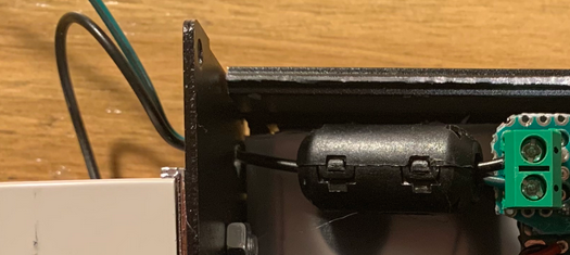
I'm struggling to see where the power for the coil comes from, I've followed the wires round and round and can't see where the power is supplied. What really obvious thing am I missing?
Have you tried a 1u capacitor between the reset pin and ground?
Layout and cable routing is important, please take some photos and post them.
Is that circuit intended to model a car ignition system with coil, mechanical points and a spark suppressing capacitor (condenser in those days) ?
The connection between the primary and secondary of the ignition coil looks odd. So does the relay coil in series with the primary side of the ignition coil. It is difficult to see how you are going to interpret the results delivered by that current sensor.
In an a classic car ignition system, the primary side of the coil is in a loop with the battery and the ignition points when the engine is switched on. The points are opened mechanically in relation to the rotation of the cam shaft (assuming it is a 4 stroke motor). If the engine is running at, say 5000 RPM, that is about 80Hz.
Okay I tossed a 2.2 uF cap (size I had handy) from the rst button to ground. There's no actual connector on this board but I checked which side of the button wasn't grounded. Unfortunately no luck on that, the behavior seems exactly the same.
I added photos here since it was going to be too large for the forum. Are those helpful?
The relay is an attempt to draw something roughly electrically equivalent to the coil. The coil in the Model T contains a transformer/relay hybrid. When the current rises enough it opens the relay.
Here is a diagram and here's a rough model I made. The ammeter signal in the model linked is actually close to what I see when the system doesn't reset itself.
Edit: Here's what it looks like in action. You can see the single-fire is at least functional but it completely fails and resets on multi. Imgur: The magic of the Internet
You need to filter every wire that comes in or goes out of the aluminum chassis. I would start with a 0.01µF cap.
The caps need to be right were the wire comes into the chassis (green circles). The length of the wire coming in before it reaches the capacitor must be < 1/16". The capacitor leads must be equally short.
BTW you should never draw a schematic with wires like in the red circle. You should separate where they cross.
That is an ancient design. I was initially assuming something more modern than that, but still predating electronic ignition. I found this: Trembler coil - Wikipedia
It appears that the opening and closing of the contacts on that trembler are independent of the speed of the engine. It is now clear why you've drawn the schematic in such a way and, in reality, the "relay" coil does not exist because the ignition coil has that function.
It is a bit like a classic magnetic buzzer with an additional coil wrapped round it to generate a pulsed high tension supply for the spark plugs.
That model is a nice illustration. I see you've dispensed with the contacts and drive the whole thing with an N channel mosfet at what I guess is the frequency of the trembler. If that 14kV is realistic, then it it is clear that there will be some interference. Is there anyway you can locate that ACS712 current sensor outside the aluminium box, in the same way that you have appeared to do with solid state relay, just taking Vcc, Ground and VIout to the outside ?
Thank you for the drawing tips. I'll make that change in the schematic and note that for the future. I will add caps to each wire crossing the enclosure.
6v6gt,
That is correct about the coil firing rate being independent of the engine speed. If it is powered it constantly charges and discharges into the spark gap until power is cut by the mechanical timer (akin the a distributor I suppose). The timing I really care to measure is the time from power on to the first spark. I can definitely locate the current sensor outside the box along with the relay. I honestly wasn't sure what was best.
As it stands with the advice given thus far I will move the current sensor outside the enclosure and add caps where each wire enters the enclosure. I very much appreciate the guidance. I will let you all know how it works out tomorrow.
For EMI, I would consider the black wire (relay common) as being the main source. I wonder if an improvement could be made just by wrapping 5 turns of the black wire only through the ferrite ring.
When there's a lot of electric field interference, shielding and keeping inputs low impedance will
greatly help. E-field couples capacitively to nearby circuitry, injecting charge/current.
An ignition system can have voltages changing by tens of kV in a few microseconds, meaning that
even tiny capacitances could inject milliamps into a nearby conductor.
If shielded the shield diverts the current direct to ground, avoiding your circuitry.
If the circuit is low impedance the induced currents lead to smaller voltages being developed.
So your reset line should have a low impedance pull up, such as 1k or even lower, and adding a
capacitor will also help as mentioned.
There can also be RF effects that the ferrites will help with.
The 3 ferrite cores are doing little or nothing because they are inside the box. There is quite a bit of cable before the core, which can radiate interference inside the box. Put them outside close to the point of entry, along with the capacitors already mentioned.
Consider the route of cables, for example the bottom right you have a cable draped on top of a circuit board, this is bound to introduce interference into the board. Cables should be routed carefully with regard to whether they might generate interference or pick it up. The 2 should be kept apart.
If you must bring the high current cables into the box they should be shielded in some way. Maybe an aluminium compartment just for those cables and the device they are connected to, to isolate them from everything else.
I'm sorry for my very delayed response. I was held up in working on this project for a bit. I wanted to report back to thank you all for your assistance as well as note what worked.
Small caps near where wires entered the enclosure were not enough for the interference I was dealing with. One important tip was to move the ACS712 current sensor outside the enclosure so none of the coil's wires were entering the enclosure. I think adding the small caps on these data lines was helpful.
The other issue I noted was that the power supply wires were the biggest source of problems (firing the coil without any of the data lines connected still caused issues with a running arduino). What I did first was to move the power supply just outside the enclosure so I could clean up the DC inside the enclosure. I put a salvaged large ferrite choke of both the 5V and GND lines right where they entered and a big 470u cap after them.
All of this made a major improvement. There's still a little flickering in the screen but it works well and the data is clean.
I am very grateful for all your suggestions. I had been struggling with this for a long time and I learned a fair bit about the problems that crop up in non-ideal electronics.
Edit: I attached a new schematic. I also thought I would link to the forum where I found this idea which includes a ton of discussion on the topic for anyone searching in the future. A new DIY electronic coil tester. - MTFCA Forum
I put a salvaged large ferrite choke of both the 5V and GND lines right where they entered and a big 470u cap after them.
All of this made a major improvement. There's still a little flickering in the screen but it works well and the data is clean.
Assuming you're only passing the wire once through the hole (1 turn), if you have the room to pass it again (2 turns), this will provide up to 400% improvement in reducing high frequency noise.


 Assuming you're only passing the wire once through the hole (1 turn), if you have the room to pass it again (2 turns), this will provide up to 400% improvement in reducing high frequency noise.