Hi all
Disclaimer: this is my second arduino project only, and the first forum topic I write (and this in a foreign language). As it comes to electronics, I'm a complete noob. So please be tolerant.
I'll describe the requirements along with the intended usage and propose the solution I came up with (before having implemented it). Comments and suggestions by the community are very appreciated.
Please refer to the attachments for clarification.
The requirements:
To save wiring as well as arduino pins, I want to be able to talk to a network of multiple devices, one at a time, over some kind of bus.
- Arduino UNO acting as (the only) bus master.
- Besides communication logic, the bus provides +5V/GND to power the devices.
- The master can switch on and off the power on the bus.
- Ability to address one device at a time.
- The such selected device provides one data line on the bus, which can be digital in, analog in or digital out (from the point of view of the master).
- Non-selected devices are disconnected from the data line.
- Total bus length >= 6m.
-
=4 slaves along the bus, each switching up to 8 devices.
- Cost effectiveness (it's a completely unnecessary hobby project after all).
- Speed is not an issue.
Intended usage: Balcony irrigation system
Each planting pot will have a moisture sensor like this one. Both the digital and analog line will be addressed as a 'device', so I'm free to use the one or the other on the arduino.
Each pot will receive water through a valve like these ones, which is operated each by a SG90 servo, which acts as a 'device', receiving pulses while being actuated (600ms or so).
2 Valves and 2 to 3 sensors are controlled by one slave (being somewhere between two pots).
Proposed solution:
Each device is addressed uniquely with 7 address bits A0 to A6.
A3 to A6 select one of the slaves - so there are up to 16 slaves possible. The design is extensible to support 32 slaves by using an additional address bit, but that would require more ICs.
A0 to A2 address one of the selected slave's devices.
The bus
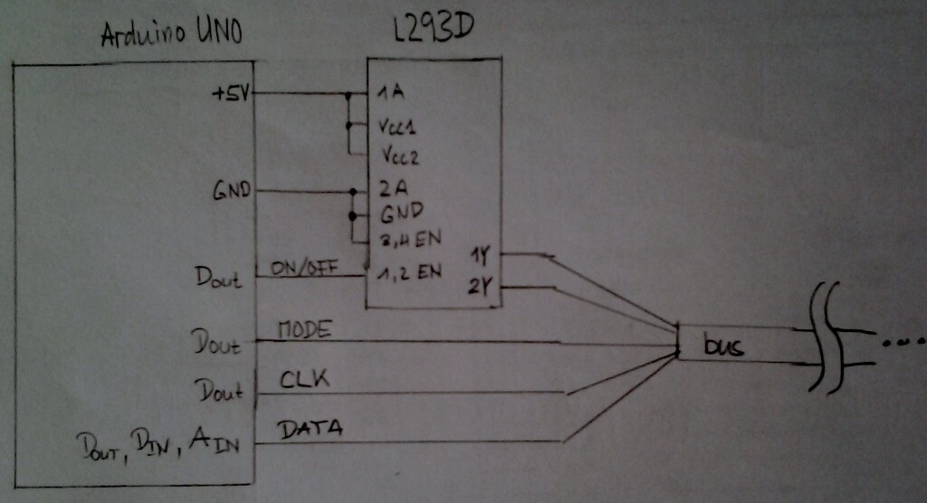
The bus has 5 wires:
- +5V
- GND
- MODE: digital output to distinguish between addressing and reading/writing.
- CLK: digital output to clock the serial transmission of the address.
- DATA: digital output for the address bits when addressing, digital or analog input when reading, digital output when writing.
The slave
Each slave is built out of 4 ICs:
- An 8-bit serial in parallel out shift register (4094). During addressing (MODE is LOW), the 7 address bits are shifted into each slaves's register through the DATA line, timed by CLK. When MODE goes HIGH, the address is available at the 4094's parallel output.
- A comparator made out of a 4 x 2-input XOR gates (4030 or 4070) and a 8-input NAND gate (4068).The XORs compare the address bits A3 to A6 to the slave's configurable bit pattern (which of course must be unique on the bus). The NAND combines those 4 comparisons and the MODE line. When the slave address matches and MODE is HIGH, the slave is selected and the NAND's output is LOW. Otherwise the slave is not selected and the NAND's output is HIGH.
- An 8-channel analog multiplexer/demultiplexer (4051), which when the slave is selected, connects a device to DATA according to the address bits A0 to A2.
The master
To power/unpower the bus, I intend to use a L293D, which happens to lay around.
A digital output pin of the arduino controls the 1,2 EN of the L293D.
The reason I want to be able to unpower the bus is to minimize corrosion on the moisture sensors.
MODE and CLK connect to digital output pins on the arduino, DATA to an analog pin, which can be used as digital or analog in as well as digital out.
Sketch of what the arduino will do once every few seconds:
power the bus;
foreach (sensor)
{
  address the sensor's digital or analog output;
  digitalRead(DATA) or analogRead(DATA) it's value and store it somewhere;
}
if (everything is happily moist)
  turn off the water pump; // not in the focus of this topic
else
  {
    foreach (valve that is not in the required position)
    {
      address the servo;
      use servo library to write the required pulses to DATA;
      delay(600); // that's enough to move it to the opposite position
    }
    turn on the pump; // not in the focus of this topic
  }
unpower the bus;
delay(a few seconds);
Addressing a device goes like this:
digitalWrite(MODE, LOW);
pinMode(DATA, OUTPUT);
foreach(addressBit in [A6..A0])
{
  digitalWrite(DATA, addressBit);
  delay(???);
  digitalWrite(CLK, HIGH);
  delay(???);
  digitalWrite(CLK, LOW);
}
pinMode(DATA, INPUT); // set DATA to high impedance
digitalWrite(MODE, HIGH);
delay(???);
// device now connected to DATA
Now I'm looking forward for your comments!
Especially interested in:
- Will it work? If not: why not?
- Am I reinventing the wheel? Is there a better off the shelve solution?
- What cabling to use? Just 5 wires? Twisted pairs? Shielded?
- What about timing? Obviously there is plenty of time, so some delays are no problem.
- Power, cable length, reliability issues?
- Optimizations?
P.S.:
Some components of the system have already proofed to work. I have a project (a window farm, that is) in operation which uses the same pump (a 12V peristaltic pump controlled with a transistor) and the same valve/servo combination. As long as only one servo is operated at a time, everything works just fine. The system is irrigated in a round robin manner on a timed bases, so no sensors and no bus either.