Hi! I'm doing my first arduino project. Basically a one-touch turn signal that will blink 3-4 times with me just pushing then releasing the stalk. It's going really well and I even got it working at my desk.
HOWEVER! The car switch has some really weird circuitry. It has one pin getting voltage from the car and 5 output pins, one of which is for both turn signals, the others for high beam, wipers, etc. The way the turn signals work with one output pin is such: the right turn signal just sends the voltage straight back to the car, while the left signal sends it over a 200ohm resistor.
My issue lies in detecting whether I'm activating left or right signal... I can't just cut the two cables and run arduino voltage through the turn signal specific circuit. That would break all other functions of the switch.
What could I do to determine which direction I'm pressing the switch?
I guess that you have to get a GND line from the car. Then measure the voltage on the output pins vs. GND to find out which pin belongs to which switch. The rest depends on the car voltage (pulldown voltage divider).
I've identified the pin, but it's only one for both indicators. And I don't know how to determine if it's just straight voltage, or it's going through a 200ohm resistor.
Does you car use computers for operation? IF so, all your switch is doing it telling the computer to do something, It is NOT directly controlling your lights.
You need to get a wiring diagram for the car , which also give you the colours of the wires .
But , as said you might not be directly controlling the indicators - it may be a signal to the ECU or Other control module .
Can you draw a schematic of how the switch is wired?
It has a single plug with 6 wires. Pin 4 is 12-14v from the car. Depending on the direction you push the switch, it connects Pin 4 to Pin 1 / 2 / 3 / 5 / 6 either directly or through a resistance. Pin 6 is the one used specifically for indicators, and nothing else.
For right indicator it connects Pin 4 and Pin 6 directly.
For left indicator it connects Pin 4 and Pin 6 over a 200ohm resistor.
If you have the left turn signal and the wipers on at the same time, the car will get voltage on Pin 6 over a 200ohm resistor, then also on some other pin that is specific to the wipers.
Put a resistor to GND and measure the voltage when one or the other button is pressed
I don't understand how this would work, wouldn't the voltage be the same, since there is no load?
Does you car use computers for operation?
you might not be directly controlling the indicators - it may be a signal to the ECU
Exactly, the switch just provides control signal. My approach is to cut the wires to Pin 4 (voltage) and Pin 6 (indicator control) and put the Arduino between the car computer and the switch. Arduino would read the switch, then with two mosfets emulate the switch behaviour, so the car's computer sees basically the same thing.
I did it and it works on my desk, but then I got it in the car and realised that while Pin 6 is specific to the indicators, Pin 4 provides voltage for all other functions... So I need a way to measure the resistance between the two in place, while 12-14 v are going through the circuit...
Have you got a schematic of the car or the indicator system.
Are you aiming for your system to work in parallel with the existing car switch system?
[soapbox]
Sounds like you are trying for a lazy lane change activation.
Can't you move the lever to get the indicator to work without it locking?
I believe I can in my Kia Rio, 2006.
The more automatic things you put in a car, the more fun you TAKE OUT of the driving experience.
[/soapbox]
I did read it, but I don't fully understand it. So I should take the signal from the switch, run it through a resistor, and into Arduino ground?
This is probably second nature to you, but I have only basic knowledge in this area, so a bit more detailed explanation or a simple schematic will be greatly appreciated!
Each Arduino input (switch output) needs a pullup (to Vcc) or pulldown (to GND) resistor. The voltage drop on these resistors is zero unless the switch is closed.
This depends if OP will continue to use the electronics in the car. If so I recommend to install the switch in the car, with everything connected. Then measure voltage of each pin switch as function of switch position. My guess is that the car electronics will have a pull up or down resistor of its own.
If the resistor in the switch is only 200 ohm, you would need a pretty low pull up down resistor (<1000 ohm). And that might screw up the car electronics.
Also, a car with 12V battery will have 14V when driving... also pretty high peaks may be present. You need to protect Arduino Vin and arduino analog pins from these peaks with special circuitry.
@barney_rubble
I may be saying the obvious, but most cars use an electrical system with a common minus on the frame or body. Therefore, all lines to loads in such a system are single-wire from the positive terminal of the battery.
Therefore, to check whether a wire is powered or not - you must measure the voltage between the wire and the car body.
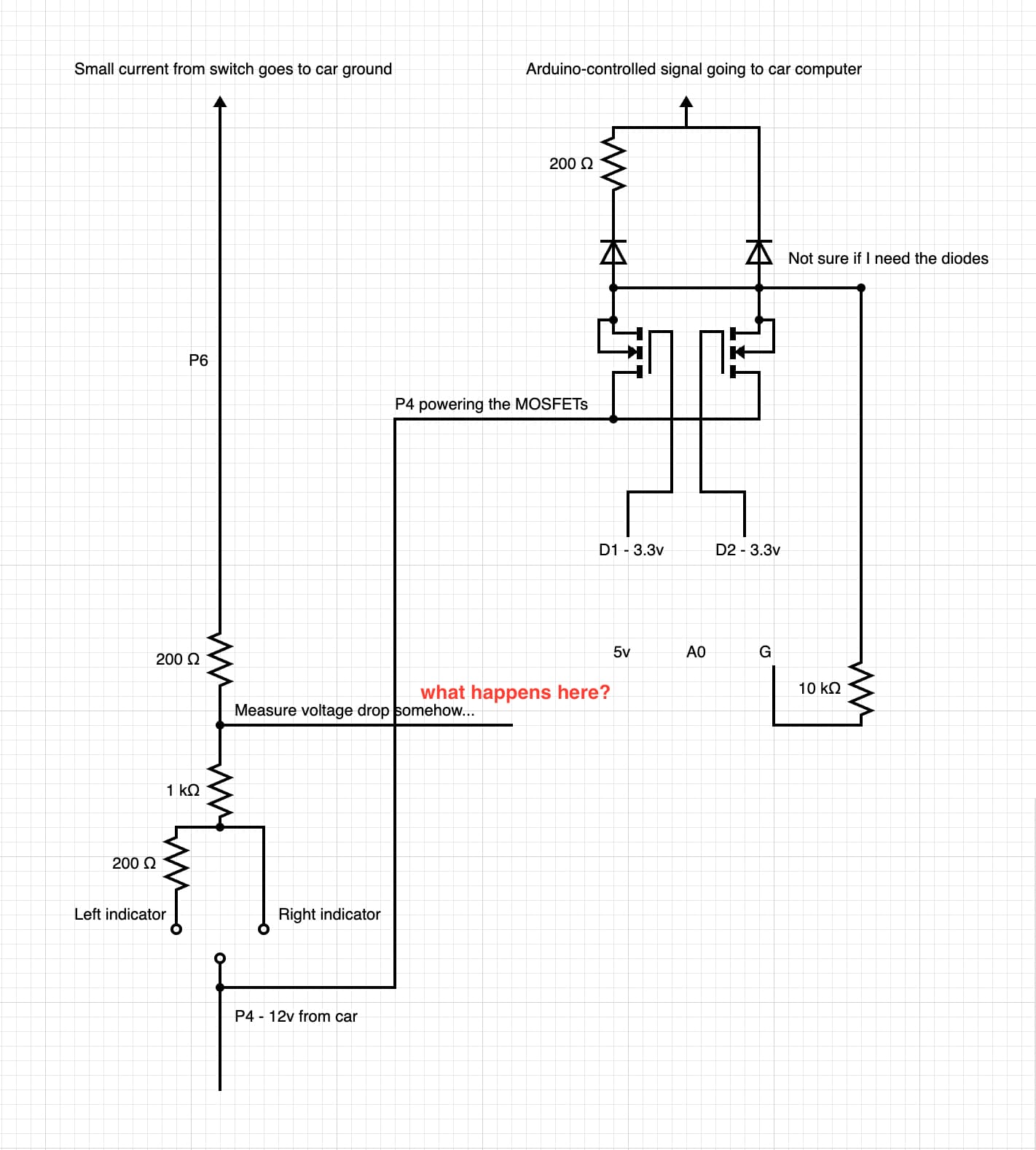
Here's basically how the switch works. Pin 4 provides power to all, and Pin 6 provides control signal to the computer to turn on the respective indicator. The other 4 pins control other functions completely separately from the indicators.
What I can't figure out despite all the tutorials I read is how I should use the voltage divider without sending 12v to arduino Ground ot A0...
Lastly... the arduino will be powered by one of those cigarette lighter adapters. Not sure what that means for the ground, the ground really messes with my mind.
You can simply connect your signal from voltage divider to a0.
You should add a capacitor to ground and a schotky diode to 5V to protect a0 pin from high voltage peaks that are always present in cars.
Why do you need an arduino anyway?
I thought the voltage divider would be enough, since it would bring even 15v down to 2.5v.
May I ask for some more details or a simple schematic? Between English not being my native language and electronics not being my strongest side, "capacitor to ground and a schotky diode to 5V" is not immediately clear to me. Also, what size capacitor & diode would work?
The Arduino will allow me to quickly press and release the switch and automatically get 3-4 indicator flashes, without holding the switch. I do a ton of driving and it's one of the things I really appreciate when driving newer cars.