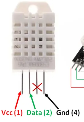
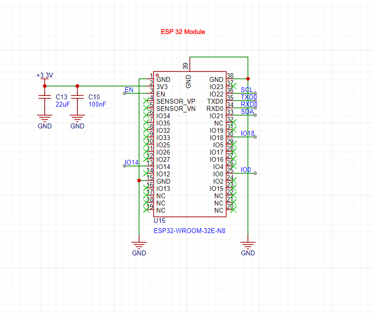
I have a PCB with a custom ESP32 on it. It is using the ESP32 WROOM 32 Chip. I connected 4 header pins for a DHT22 sensor. The data pin selected was IO14 and it was pulled up to 3.3V using a 10k ohm resistor.
I have the DHT22 sensor module that already has a 10k ohm resistor and a decoupling capacitor. I've tried connecting it to the header pins and even removed the 10k ohm resistor on the PCB. I'm still not getting any readings. The sensor is working though. I've tested it on another board. What could be the issue? My Arduino IDE code also references pin 14 for the data pin of the sensor.

the code i'm using is below:
#include <WiFi.h>
#include <Wire.h>
#include <Adafruit_GFX.h>
#include <Adafruit_SSD1306.h>
#include <Adafruit_Sensor.h>
#include <Adafruit_INA219.h>
#include <DHT.h>
#include <ThingSpeak.h>
Adafruit_INA219 ina219;

#define SCREEN_WIDTH 128 // OLED display width, in pixels
#define SCREEN_HEIGHT 64 // OLED display height, in pixels

// Declaration for an SSD1306 display connected to I2C (SDA, SCL pins)
Adafruit_SSD1306 display(SCREEN_WIDTH, SCREEN_HEIGHT, &Wire, -1);

#define DHTPIN 14     // Digital pin connected to the DHT sensor
#define DHTTYPE    DHT22     // DHT 22

DHT dht(DHTPIN, DHTTYPE);

//declaring variables
float t = 0;
float h = 0;
float shuntvoltage = 0;
float busvoltage = 0;
float current_mA = 0;
float power_mW = 0;

//connecting to Thingspeak using WiFi
const char* ssid = "YWCA311";
const char* pass = "Ywca311#";
// const char* server = "api.thingspeak.com";

WiFiClient client;

unsigned long myChannelNumber = 1;
const char* myWriteAPIKey = "447LYEUNI1P4M6FR";

// Timer variables
unsigned long lastTime = 0;
unsigned long timerDelay = 30000;

void setup() {
  Serial.begin(115200);

  Serial.println("Connecting to ");
  Serial.println(ssid);
  WiFi.begin(ssid, pass);
   // Connect or reconnect to WiFi
  if(WiFi.status() != WL_CONNECTED){
      Serial.print("Attempting to connect");
      while(WiFi.status() != WL_CONNECTED){
        WiFi.begin(ssid, pass);
        delay(5000);
      }
      Serial.println("\nConnected.");
  }

  ThingSpeak.begin(client);  // Initialize ThingSpeak

  //initialise DHT sensor
  dht.begin();
  // initialise ina219 with default measurement range of 32V, 10A
  ina219.begin();

  if(!display.begin(SSD1306_SWITCHCAPVCC, 0x3C)) {
    Serial.println(F("SSD1306 allocation failed"));
    for(;;);
  }

  delay(2000);
  display.clearDisplay();
  display.setTextColor(WHITE);
}

void loop() {
  delay(4000);

  //read temperature and humidity
  float t = dht.readTemperature();
  float h = dht.readHumidity();
  if (isnan(h) || isnan(t)) {
    Serial.println("Failed to read from DHT sensor!");
  }

  if (! ina219.begin()) {
    Serial.println("Failed to find INA219 chip");
    while (1) { delay(10); }
  }
  // read data from ina219
  shuntvoltage = ina219.getShuntVoltage_mV();
  busvoltage = ina219.getBusVoltage_V();
  current_mA = ina219.getCurrent_mA();
  power_mW = ina219.getPower_mW();

  // show data on OLED

  //clear display
  display.clearDisplay();

  // display temperature & humidity
  display.setTextSize(1);
  display.setCursor(0,0);
  display.print("Temperature: ");
  display.setTextSize(2);
  display.setCursor(0,10);
  display.print(t);
  display.print(" ");
  display.setTextSize(2);
  display.cp437(true);
  display.write(248);
  display.setTextSize(2);
  display.print("C");
  display.setTextSize(1);
  display.setCursor(0, 30);
  display.print("Humidity: ");
  display.setTextSize(2);
  display.setCursor(0, 40);
  display.print(h);
  display.print(" %");
  display.display();


  delay(4000);
  display.clearDisplay();

  // display INA219 voltage values
  display.setTextSize(1);
  display.setCursor(0,0);
  display.print("Bus Voltage: ");
  display.setTextSize(2);
  display.setCursor(0, 10);
  display.print(busvoltage);
  display.print(" V");
  display.setTextSize(1);
  display.setCursor(0, 30);
  display.print("Shunt Voltage: ");
  display.setTextSize(2);
  display.setCursor(0, 40);
  display.print(shuntvoltage);
  display.print(" mV");
  display.display();


  delay(5000);
  display.clearDisplay();
  // display INA219 current and power values
  display.setTextSize(1);
  display.setCursor(0,0);
  display.print("Current: ");
  display.setTextSize(2);
  display.setCursor(0, 10);
  display.print(current_mA);
  display.print(" mA");
  display.setTextSize(1);
  display.setCursor(0, 30);
  display.print("Power: ");
  display.setTextSize(2);
  display.setCursor(0, 40);
  display.print(power_mW);
  display.print(" mW");
  display.display();
  delay(2000);


  //set Thingspeak fields with values
  ThingSpeak.setField(1, t);
  ThingSpeak.setField(2, h);
  ThingSpeak.setField(3, busvoltage);
  ThingSpeak.setField(4, shuntvoltage);
  ThingSpeak.setField(5, current_mA);
  ThingSpeak.setField(6, power_mW);

  // Write to ThingSpeak. There are up to 8 fields in a channel, allowing you to store up to 8 different
  // pieces of information in a channel.  Here, we write to field 1.
  int x = ThingSpeak.writeFields(myChannelNumber, myWriteAPIKey);

  if(x == 200){
    Serial.println("Channel update successful.");
  }
  else{
    Serial.println("Problem updating channel. HTTP error code " + String(x));
  }
    lastTime = millis();

}
type or paste code here