The code runs perfectley on Matrix 1.
But when i replace it with the Matrix 2 only the first module is displayed correctly, the rest is displaying some weird shit, all LEDs are powered on!
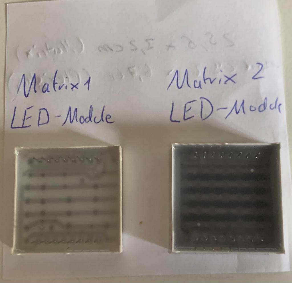
What i noticed: Matrix 1 LED-modules look different than the Matrix 2 LED-modules. What is the difference between these LED-modules?
More observations:
When i replace LED-modules on the second Matrix with LED-Modules from Matrix 1, these LED-modules work perfectly!
OK, re-plug the modules in the second matrix that are not working properly, rotated 180°.
If that does not resolve the problem, we must assume that the modules are actually mis-labelled 1088B matrix modules which will not operate properly either way around.
Playing swaps: Presumably the offending modules exhibit the same behaviour when plugged into the first, otherwise working board or the apparently working position on the second.
So i swapped the modules, the second Matrix-LEDs just seem to be broken.
They dont display correctly on the first max7219 either, they just all light up again.
Than i tried rotating the matrix-LED. As you can see in the picture, they still seem to be broken.
The difference is in the way the LEDs (which are diodes) are wired up in the modules. One has a common positive pin, the other a common negative pin. They are not interchangeable.
The result of your 180° rotation confirms that they are indeed, 1088B displays. If labelled 1088A, that is clearly a manufacturing error. It is suggested that they may be factory rejects intercepted and fraudulently labelled by someone, perhaps a factory worker.
What i already tested:
-The Modules from the 16x64 Matrix are fine, they work on an other Matrix completeey fine!
-Modules from a working Matrix arent working on the 16x64.
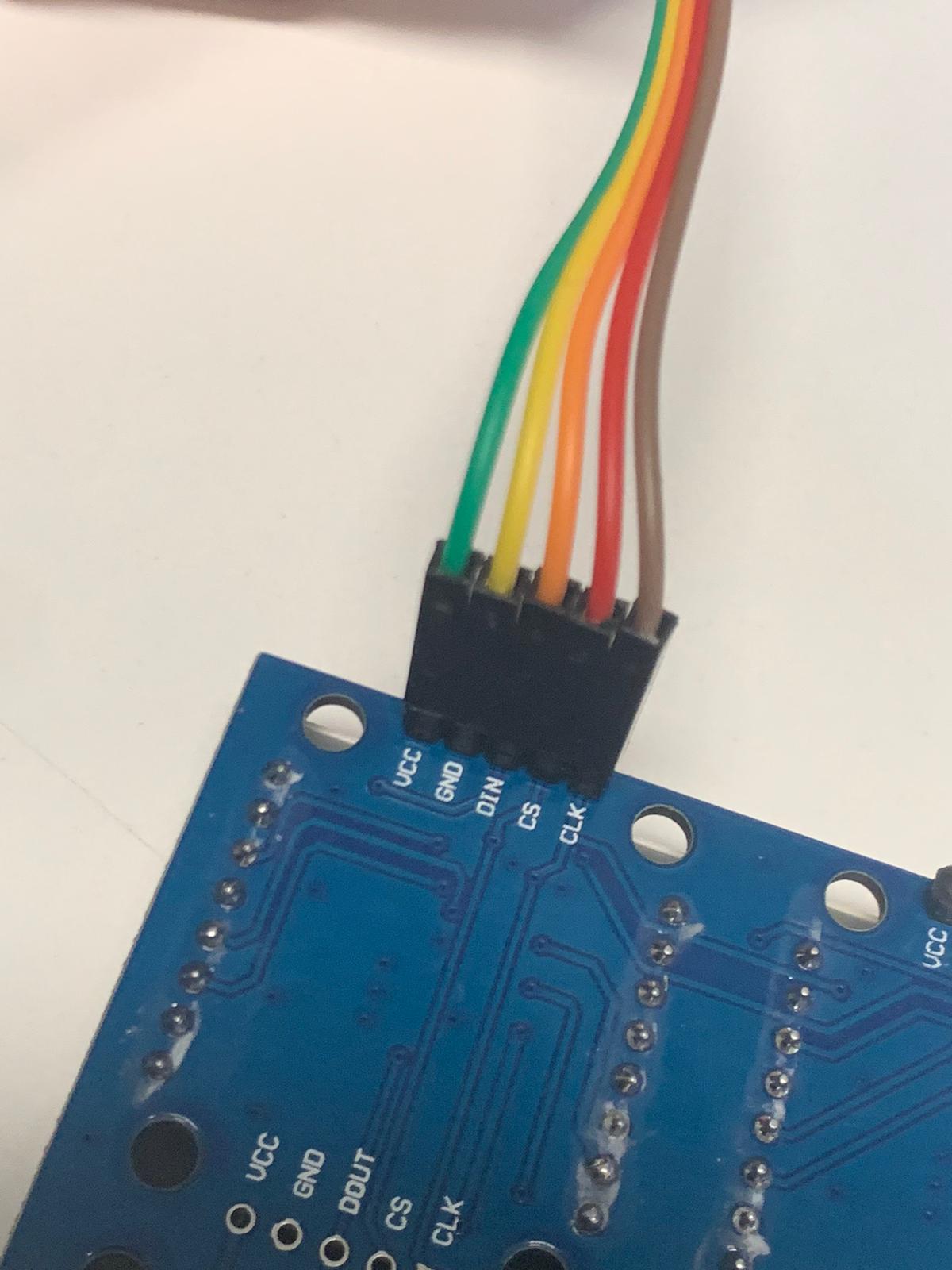
The code i used is the MD_MAX72XX_HW_Wrapper with the following config of wiring:
// Hardware definition
#define CLK_PIN   14  (SD3 on ESP8266)
#define DATA_PIN  13 (D7 on ESP8266)
#define CS_PIN    10 (D5 on ESP8266)
So in fact, you could use the modules from this matrix to replace the wrong ones from the second matrix in your first enquiry - at least as a test.
I was inclined to wonder what would happen if you took the incorrect 1088B modules from the rogue matrix and tried them in this one, but looking at your last image
This definitely is an FC-16 design (variant - two rows) so should have the code configured as such. If it does not work with the correct code, then you have a wiring fault whether in your connections or in the module itself.
Have you tried swapping the modules between the lit and unlit sections of this array; what happens? Note that it is a good idea to have a 10k pull-up on either "DIN" or "CS" when using the MAX7219.
Nothing happens, when i switch matrices from the lid-section and the non-lid-section, still only the right section lids up.
I also tried adding a 10k, but nothing changes.
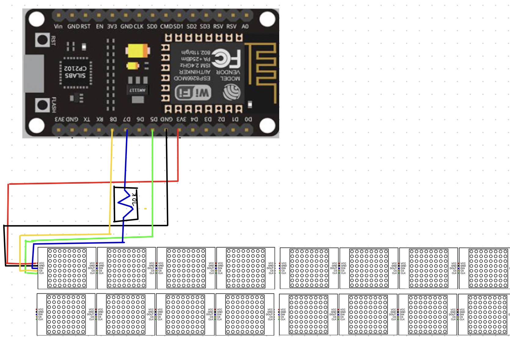
I did a quick sketch of the wiring:
I tried multiple different code-snippets, here is the code used for testing: `#include <MD_Parola.h> #include <MD_MAX72xx.h> #include <SPI.h>
#define MAX_DEVICES 16
#define CLK_PIN D5 // or SCK #define DATA_PIN D7 // or MOSI #define CS_PIN D8 // or SS
#define HARDWARE_TYPE MD_MAX72XX::FC16_HW
MD_Parola P = MD_Parola(HARDWARE_TYPE, DATA_PIN, CLK_PIN, CS_PIN, MAX_DEVICES);
void setup(void)
{
P.begin();
}
void loop(void)
{
P.print("Hello");
} `
What i wonder: I order two Matrices from different sellers with good Reviews and both are faulty? Im doubting my skills in programming now
Have a good sunday!
Well that indicates that the LED modules are themselves functioning. Did you try putting them in the other ("your "second") module with the 1088B matrices?
There is some concern that MAX7219s powered by 5 V may not respond properly to 3.3 V logic from an ESP8266 (page 3 of the datasheet) though I have had no problems and your diagram suggests that you are actually powering them from 3.3 V which introduces two problems - firstly they are not specified to operate at 3.3 V (again, page 2 of the datasheet) though others report them working fine from a 3.7 V LiPo battery as you would expect with red LED arrays (which do not take as much voltage as green or blue) since they are CMOS devices . The second concern is that attempting to power a 16 module array from the 3.3 V line of a NodeMCU will overload the regulator.
You should be testing this with a 5 V Arduino such as a Nano, powered from a 5 V power supply to the "5V" pin. And my suggestion, FWIW, was a 10k pull-up, not a series resistor.
It really does sound like either a wiring fault or a dead MAX chip. Check the soldering of the first chip.
I am tossing up whether to order one of these 8 by 2 arrays just for fun. (From a slightly cheaper Vendor on Aliexpress. I cannot find them at all on eBay. Mind you, I prefer green ones!)