The project that I am making is a regulated load that can be controlled with Arduino.
The maximums are:
100V
20A
I'll be using an N channel MOSFET NTP095N65S3HF, I will put 10 fets parallel in total to maximize the 2kWatt that will be produced if the maximum will be running through them.
but I am a bit stuck with how I will be able to control all ten of them with Arduino. I came up with two ideas but I am not so sure if they will actually work.
The idea is that you can put in the amount the PSU gives and with the information that it gets it will control if the sensors read the right amount. With a threshold of 1v+ and 0.05A, it will stop the simulation.
What kind of load do you want to simulate: resistive, constant current, or what?
How do you want to control the current through the MOSFETs? For PWM a single transistor is sufficient, but for analog control you have to care for equal distribution of the current on then 10 MOSFETs.
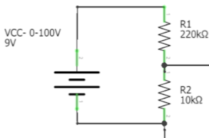
The sensors that I will be using are an Iduino ME067 and I was planning to get a maximum of 5v using resistance that will go straight to Arduino. And in the code, I'll just multiply the voltage.
There will be two options. A constant and a dynamic current. It's for testing if a PSU is still useable or okay. (The simulation might be running up to 8 hours if possible)
Because the total wattage will be 2k and one of the MOSFET has a max of 272W.
That's the part I am a bit stuck at. On how I will control the 10 FETS accurately with only Arduino.
Make a little wiring. Your text "maximum of 5 volt using resistors" confuses me.
Do You intend to measure the 100 volt line?
Using PWM to the FETs it will in principle be either 100 volt or 0.
For that rating you have to guarantee 25°C on the heat sink, how do you want to dissipate 2kW at that temperature? Fresh water cooling of a giant heat sink?
Feed the sensor with 5 volt. Then it will give the output I told in reply #8.
That 5 volt can likely be tapped from the controller 5 volt. Use a good Vin of 9 volt, not the fire alarm rectangular cell.