Digital Tape Measure Decoding Serial Data

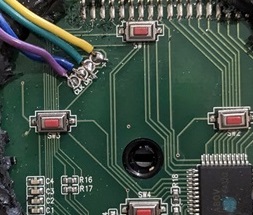
Hello, I am trying to decode the data from a digital tape measure. It is an eTape 16 which uses an incremental rotary encoder and an optical encoder with a metal tape. here's the protocol for the tape and here's the protocol for the rotary encoder. Here's a block diagram for the entire unit. I would like to display the eTape results on an OLED, I am new to Arduino and coding but I was able to put together Arduino code which can read a digital caliper, but not sure how to write the code to read this tape measure. Here Proto_G Engineering made a nice video of how to disassemble the exact same tape measure and how it works, which I was able to do and found +, -, clock and data pads on the circuit board which I soldered wires to, and brought them out of the case when I re-assembled the unit. I hooked it up to an oscilloscope and it looks like both the clock and data have a matching output with a series of Runt type pulses which I can't find a pattern to be able to design Arduino uno code to read them. The clock and data pulses don't seem to have a consistent bit sequence and I found it easier to look at the data when I have my scope on roll. I created a sketch to read the basic cheap 8" calipers but their 24 bit code is very straight forward and easy to read with the Arduino thanks to a video by Curious Scientist who does a great job explaining and showing the clock and data signal on an oscilloscope. I read the patent for the tape measure, so I know it uses the exact encoder primarily and the rotary encoder for re-confirmation every 3 inches but I am not sure how to modify the basic caliper code to work with this device. Does anyone have any advice on possible Arduino code to read a digital tape device? Any help would be appreciated.

Credit to Proto G for his video and comments on this tape and for finding the patent info.
Credit to Curious Scientist for his video showing the data stream info and a circuit using a logic level shifter and voltage regulator to be able to interface the lower voltage caliper with the Arduino.
Credit to cbm80amiga for his video showing the circuit using a level shifter and buck regulator as well as pinouts for basic caliper reading.

Again, I am trying to decode a digital tape (eTape 16) but decided to start with a caliper, as there is a lot of info out there for calipers and I needed to start somewhere. I will include the code below that I am using to decode my caliper. I started with a Johnson caliper but had issues with the clock and data wires getting yanked off so I switched to a Clockwise brand caliper as it has a micro usb data port which is easier to work with. My sketch shows the caliper in real time and a message at the top asking to enter a length and below that, a note that says "En = Enter" which is the first of two buttons that I am using. The point of the circuit and code is to mount the eTape to my compound miter saw and use it to measure boards to cut at different lengths. The Oled screen will be up by the handle and easier for me to read. When you press "En" the length will be placed on the screen above the active caliper reading and won't change until I press "Clr". I can still pull the tape out and re-check the measurement against the one I entered as the tape will continue to read in real time. After I cut the piece, I press "Clr" and start a new measurement on a new piece. Again, thanks to everyone in advance for help on this as I scoured the internet for any Arduino code info for digital tapes using an actual metal tape (not laser) but couldn't find anything. I apologize if my coding is not formatted correctly, I am still learning how and where to place the curly braces. Also, I have not posted before so I hope this is the correct place to post this.

#include <Adafruit_GFX.h>
#include <Adafruit_SSD1351.h>
#include <SPI.h>
#include <math.h>
#include <Wire.h>

#define SCREEN_WIDTH 128
#define SCREEN_HEIGHT 128

#define SCLK_PIN 2
#define MOSI_PIN 3
#define DC_PIN   4
#define CS_PIN   5
#define RST_PIN  6

#define CLOCK_PIN1 8 // Pin definitions for the first caliper
#define DATA_PIN1  9
#define ENTER_BUTTON_PIN A1 // En  = the Enter button
#define CLR_BUTTON_PIN A0   // Clr = the Clear button

float firstNumber = 0.0;
float secondNumber = 0.0;
bool firstNumberEntered = false;

bool readCaliper1();


float result1 = 0.0;

float lastResult1 = -1.0; // Store last displayed values


#define BLACK   0x0000
#define BLUE    0x001F
#define RED     0xF800
#define GREEN   0x07E0
#define CYAN    0x07FF
#define MAGENTA 0xF81F
#define YELLOW  0xFFE0
#define WHITE   0xFFFF

Adafruit_SSD1351 display = Adafruit_SSD1351(SCREEN_WIDTH, SCREEN_HEIGHT, CS_PIN, DC_PIN, MOSI_PIN, SCLK_PIN, RST_PIN);

void setup() {
  pinMode(CLOCK_PIN1, INPUT);
  pinMode(DATA_PIN1, INPUT);
  
  pinMode(ENTER_BUTTON_PIN, INPUT_PULLUP);
  pinMode(CLR_BUTTON_PIN, INPUT_PULLUP);

  Serial.begin(115200);

  display.begin();
  display.fillScreen(BLACK);
  display.setCursor(0, 0);
  display.setTextColor(YELLOW);
  display.setTextSize(2);
  display.println("Sketch"); 
  display.println("Test #2");
  delay(2000);
  display.fillScreen(BLACK);
  display.setCursor(0, 0);
  display.setTextColor(BLUE);
  display.setTextSize(2);
  display.print("Ent Length");
  display.setCursor(0, 20);
  display.setTextColor(WHITE);
  display.setTextSize(2);
  display.print("En = Enter");
  
}
char buf[20]; 
unsigned long tmpTime1; 
int sign1; 
int inches1; 
long value1; 

void loop() {

  if (digitalRead(ENTER_BUTTON_PIN) == LOW) {
    enterButtonPressed();
    delay(200); // Debounce delay
  }
  if (digitalRead(CLR_BUTTON_PIN) == LOW) {
    clrButtonPressed();
    delay(200); // Debounce delay
  }

  // Read caliper
  while (digitalRead(CLOCK_PIN1) == LOW) {}
  unsigned long tmpTime1 = micros();
  while (digitalRead(CLOCK_PIN1) == HIGH) {}
  if ((micros() - tmpTime1) < 500) return;
  readCaliper1();
  char buf[20];
  dtostrf(result1, 6, 3, buf + 1); strcat(buf, " in ");
  dtostrf(result1 * 2.54, 6, 3, buf + 1); strcat(buf, " cm ");
  //Serial.print(result1, 3);
  Serial.print(convertDecimalToFraction(result1));//Prints a fractional number on serial monitor
  Serial.println(" (Caliper)");


  // Only update the display if the value has changed
  if (result1 != lastResult1) {
    display.setCursor(0, 99);
    display.setTextColor(BLUE);
    display.setTextSize(1);
    display.print("Caliper Length");
    display.fillRect(0, 111, SCREEN_WIDTH, 16, BLACK);
    display.setTextSize(2);
    display.setCursor(0, 111);
    display.setTextColor(BLUE);
    display.print(convertDecimalToFraction(result1));
    lastResult1 = result1; // Update last displayed value
  }
}

void enterButtonPressed() {
    display.setTextSize(2);
    display.setCursor(0, 48); 
    display.setTextColor(WHITE, BLACK);
    display.print("Entered");
    display.fillScreen(BLACK);

  if (!firstNumberEntered) {
    firstNumber = result1; // Use caliper reading
    display.setCursor(0, 67);
    display.setTextColor(BLUE);
    display.setTextSize(1);
    display.print("Caliper Length");
    display.fillRect(0, 79, SCREEN_WIDTH, 16, BLACK);
    display.setTextSize(2);
    display.setCursor(0, 79);
    display.setTextColor(BLUE);
    display.print(convertDecimalToFraction(result1));
    delay(2000);
    display.setCursor(0, 20);
    display.setTextColor(WHITE);
    display.print("C = Clr");
  
  }
}

void clrButtonPressed() {
  displayPrompt("Cleared");
  delay(2000);
  resetDisplay(); // Reset display and start again
}

void displayPrompt(const char* prompt) {
  display.fillScreen(BLACK);
  display.setCursor(0, 0);
  display.setTextColor(GREEN);
  display.setTextSize(2);
  display.print(prompt);
}

void resetDisplay() {
  display.fillScreen(BLACK);
  display.setCursor(0, 0);
  display.setTextColor(BLUE);
  display.setTextSize(2);
  display.print("Ent Length");
  display.setCursor(0, 20);
  display.setTextColor(WHITE);
  display.setTextSize(2);
  display.print("En = Enter");
  delay(4000);
 
}

String convertDecimalToFraction(float value) {
  int whole = (int)value;
  float fraction = value - whole;

  int denominator = 16; //16 for 16ths, 32 for 32ths, 64 for 64ths and so on
  int numerator = round(fraction * denominator);

  // Reduce the fraction 
  int gcd = findGCD(numerator, denominator); 
  numerator /= gcd; 
  denominator /= gcd; 

  if (numerator ==0) { 
    return String(whole) + "\""; // Add quote symbol
  } else if (numerator == denominator) { 
    return String(whole + 1) + "\""; 
  } else {
    return String(whole) + "-" + String(numerator) + "/" + String(denominator) + "\""; // Add quote symbol 
  }
 } 
      
 int findGCD(int a, int b) { 
     if (b == 0) 
       return a; 
      return findGCD(b, a % b); 
 }

bool readCaliper1()
{
  sign1 = 1;
  value1 = 0;
  inches1 = 0;
  for (int i = 0; i < 24; i++) {
    while (digitalRead(CLOCK_PIN1) == LOW) {}
    while (digitalRead(CLOCK_PIN1) == HIGH) {}
    if (digitalRead(DATA_PIN1) == HIGH) {
      if (i < 20) value1 |= (1 << i);
      if (i == 20) sign1 = -1;
      if (i == 23) inches1 = 1; 

    }
  }
  result1 = (value1 * sign1) / (inches1 ? 2000.0 : 100.0); 
 
}

When you say you tapped into +, -, clock, data, it is unclear what clock and data lines you are talking about. There are 2 encoders feeding into the circuit board and the IC has to interpret both of them to figure out where it is at.

What exactly are you trying to do? If you just want the display up by the handle of your saw, it may be easier to simply extend the connection between the tape measure IC and the OLED so you don't have to do any decoding at all.

Hello blh64, thanks for your interest. On the circuit board, there are copper pads that look like test points that say "clock" and "data" and they trace directly back to the Abov semiconductor chip MC96F6432Q. "clock" traces to pin 36 (DSCL) and "data" to pin 37 (DSDA). I would like to decode the serial data from the tape if possible, extending the SPI info for the LCD would be a last resort. I really want to understand more of how this device works which would give me more control for any future projects as I have a half dozen of these tapes.

If you look at the data sheet for that chip

You will see that it is a lot like an arduino chip (8 bit micro controller) and the DSCL/DSDA lines are for doing on chip debugging. They don't have anything to do with data transfer between the encoder and the MCU or the MCU and the display.

If you want to decode the encoder signals, you will have to do more reverse engineering and figure out which pins are being used.

I didn't think about that, I just saw clock, data and power test points together and thought I got lucky. Especially since they seem to send serial data when the tape is being moved in or out. I will trace back where both the encoders end up. Thank you again for your interest, it's very helpful to have someone else see something that you have been staring at for months and didn't see.

Do a Google search.
There are plenty of reverse engineered sites with how to and details of the coded signal from all types of calipers.
Yuri's toys being just one.

Hello bluejets, yes Yuriy's toys is a good site, but all the sites seem to be about DRO's with relatively short linear runs. I am trying to decode the 16-foot digital tape measures which don't use the standard 24-bit sequence like the calipers and DRO's use. I can't seem to find any info on Arduino code to decipher their output.

You don't need Arduino code to decypher the output, you need a CRO.

UPDATE: There are 6 absolute encoder pins that go to the PWM pins on the microcontroller and the optical encoder has 2 pins that go to a PWM pin and SCK1. But I started to focus on the LCD and noticed that it operates on a/c voltage which means it is multiplexed. I think it uses 4 com pins and the rest (15 pins) are segments for a total of 19 pins. The voltages on the pins range from .5, .8, 1.0, 1.3, and 1.6 depending on which digit is lit. Still working on which pins are for which segments.

UPDATE: I hooked up my scope and confirmed that there are 4 common pins, and the rest (15 pins) are for segments. The voltages on the com pins range from 0v, .92v, 1.80v and 2.83v. So, this is a 1/4 duty 1/3 bias LCD design. I am going to try to write Arduino code to intercept the pins from the microcontroller driving the multiplexed LCD and decode them to drive an OLED using either SPI or I2C communication. I think this could be easier than trying to use the encoder outputs straight to the Arduino and completely rewriting the code, bypassing the built-in microcontroller and LCD, as there are timing functions built into this devices programming which I am not sure I can get right. I will post more when I make some progress.

Hi Jaymccoll, I'm working on the same exact project and I was wondering if you had any luck to make it work?

Hi navid360, I am having trouble, I wrote different code to read the com and segment pins but not having luck getting my new Arduino code to decode the lcd data. I soldered wires onto the lcd pins and ran them into an Arduino Mega 2560, which has plenty of I/O options. Also, while I am sure I have the com pins identified, I don't know which segment pins do which segments. Typically, 2 segment pins will handle 8 segments when there are 4 common pins (one 7 segment digit plus something else) but I haven't mapped it yet. I am now thinking about using the 6 encoder inputs straight into the Arduino along with the optical encoder input and trying to write code to decode that, which would then take the place of the built-in microprocessor that this tape uses, and give me a lot more control over the circuit which would allow me to use an oled or a standard lcd, or anything but this difficult to use multiplexed lcd. I did not think this would be so difficult to hack, have you made any progress?

Hi Jaymccoll, I didn’t go as far as you did. At first, I tried using the data and clock lines in the hope of extracting some meaningful information, but I didn’t have much success. I considered attempting to read data directly from the display, but I eventually abandoned the idea as I don’t have a lot of free time. I’ve now ordered a different digital tape measure that uses coded strips, and I’m hoping its performance will be closer to that of standard calipers. 2-in-1 Digital Tape Measure - Ft/Ft+in/in/M 16Ft Tape Measure, Backlit Display USB Rechargeable Tape Measure with Display, 20 Groups Historical Memory ACPOTEL (Blue) : Amazon.co.uk: Business, Industry & Science

Let me know if you make any progress. Just a heads up, that tape has no visible screws, you will have to break the glue on the rubber casing to get to the screws. I bought that tape also thinking it might be easier but after opening it up, I wound up going back to the first tape as the circuit board is more readily accessible.

Thanks for the heads-up! Does the PCB have CLK and DATA? If it does, could you help me identify their location on the outer case so I can just make a hole in the case instead of opening it up entirely?

It does not, the outer circuit board only contains the button inputs and some small potentiometers. The circuit board with the processor is under the lcd, which I stopped short of pulling out. I was hoping since it used a usb charging port that it also contained CLK and DATA signals, but I couldn't read any. This tape is packaged tighter, so it seems a little harder to get at stuff for testing.

This topic was automatically closed 180 days after the last reply. New replies are no longer allowed.