You could measure the time that is used by digitalWrite().
You can use my millis_measure_time.ino sketch and replace analogWrite() with digitalWrite() in three places.
I did not test it myself, but I know from the past that it is 5 µs.
The ATmega328p only needs 0.125 µs to change a pin. The 5 µs is Arduino overhead.
The SPI code uses the SPI hardware of the ATmega328p, and uses even "inline" code to control the hardware. That is very little overhead.
So everything seems just as it should be. If you want to know exactly what is going on, then you should read the assembly code that is generated by the compiler.
If you change something in other parts of the sketch, then the compiler could decide to optimize this code in a different way, and that could change the timings.
As 7 uS are a quite long time to get 2 adresses and read/modify/write a byte for a 16MHz MCU, I spend some minutes to write the below lines to evaluate the duration ;
Function digitalSet() seems to be doing same operations than digitalWrite() ; digitalSet is not "pure" assembly langage so should be far slower than digitalWrite();
Here I see assembly code slower than compiled C++ ; I had a similar issue with the powerup time on ESP66 who is far too long to allow real lowpower applications.
8µs is suspicious, because the micros() function is accurate to 4µs for an Arduino Uno.
It turns out that it was a flaw in my sketch, I will try to make a new version on Github later on.
Below is a accurate test.
I think the digitalWrite() has been improved, because I measure 3.2 µs for digitalWrite().
// Test how long digitalWrite is with an Arduino Uno
// Timer0 is used by Arduino and that is still running.

// The macro X1000 executes something 1000 times.
#define X10(a)      a;a;a;a;a;a;a;a;a;a
#define X1000(a)    X10(X10(X10(a)))

// Using global or local variables or constants make a difference for the time.
const byte pin = 13;
byte level = HIGH;

void setup()
{
  Serial.begin( 9600);
}

void loop()
{
  unsigned long t1, t2, result;

  t1 = micros();
  X1000(digitalWrite( pin, level));       // The function under test is called 1000 times
  t2 = micros();
  result = t2 - t1;

  Serial.print( result);
  Serial.println( " ns");

  delay( 500);
}
I made an update to 1.8.9 with absolutely no changes...
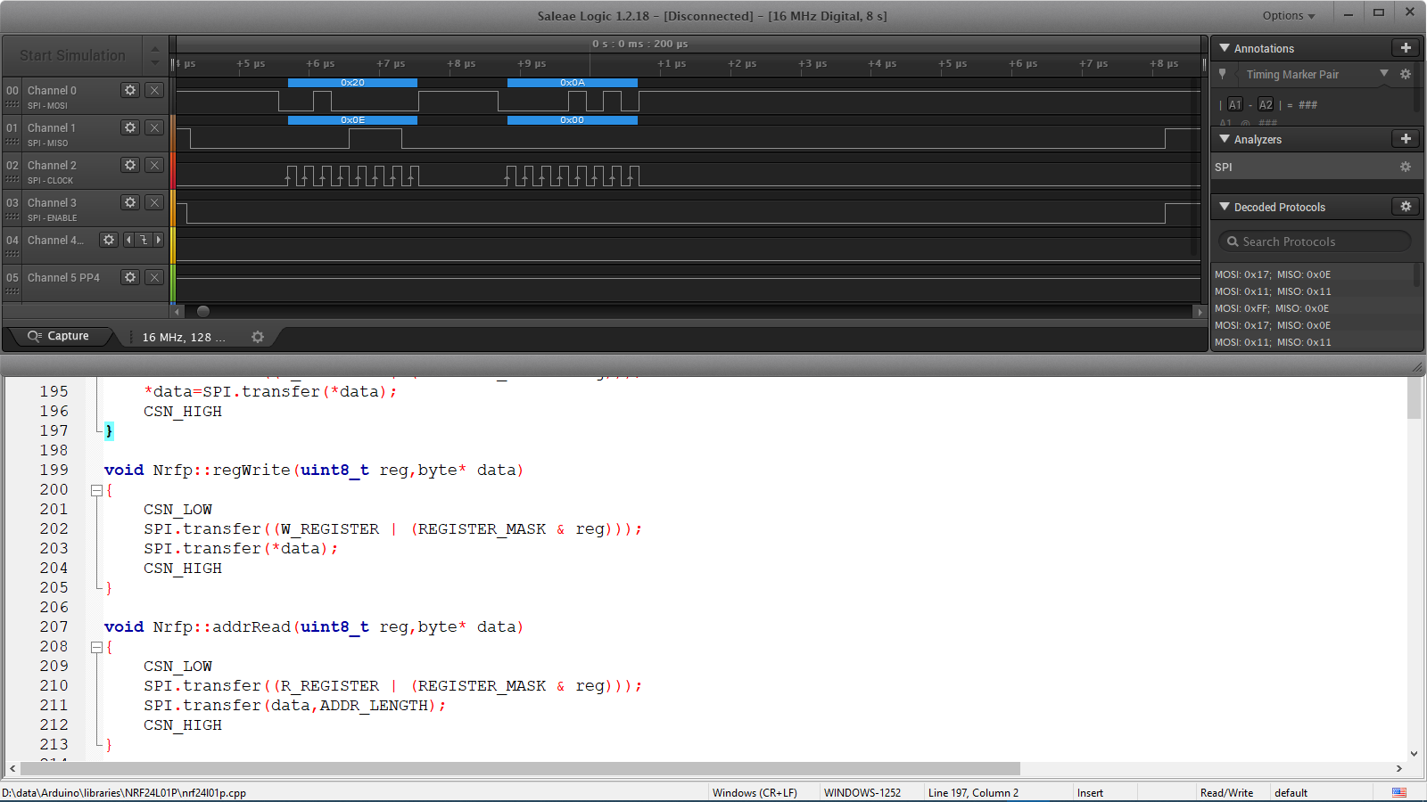
Can you have a look on the logic analyser window (attached to my first post) ?
About 1 uS from end of transmission to start of next transmission. I guess there is not a different delay from end of SPI.transfer to digitalWrite() beginning.
About 7 uS from end of transmission to CS high ; so digitalWrite means "at least" 6uS + the time to "return" after setting of CS. 8uS seems not so suspicious...
If there is a way to improve to your 3,2uS , I'm very interested.
Some times compiler are optimizing repeated sequences ; that why I put variable code inside the loop.
That is the open source code of digitalWrite(). The highlighted line is at the top.
The AVR microcontrollers have a special assembly instruction to change an output pin. That is the "direct port manipulation" and takes 125ns. You can use that in your code, or use the digitalWriteFast, which is trying to do that if everything is known during compilation.
The Arduino macro bitSet() and bitClear() can be used with a register and are translated into the 125ns direct port manipulation.
The SPI.transfer() function has to return, and the Arduino digitalWrite() changes the pin at the end of the function. Perhaps an extra microsecond for the variable 'csnPin' and then there are still 2 µs that I don't know Perhaps an extra microsecond because the Arduino optimizes for size instead of speed. The remaining microsecond is within the margin of error
Why all the hand wringing over a couple of microseconds at the end of a library function? Either tell us why ~4 microseconds really matters or it’s just an academic exercise.
If those few microseconds matter that much to your application, you should determine how much of the time you think is being wasted is actually due to the SPI transfer and how much is under your control with the toggling of the CS pin. Only then can you decide which bits of code need attention but most importantly, is it even possible to realize a reduction in the time required when using a hardware based function.
Frankly, this thread has all the classic signs of being an x-y problem.
You can toggle IO pins with a write to the PINx register, only takes 1 clock cycle.
So:
PINB = 0x00000100; // toddle D10 to low on a 328P, make sure you know it was high before this
SPDR = yourdata; // clocks out the data
nop;nop;nop;nop;nop;nop;nop;nop;nop;nop;nop;nop;nop;nop;nop; // wait for data to clock out, vs waiting for interrupt
PINB = 0x00000100; // toddle D10 on a 328P // CS back high
Using this method, you send out a byte in about 20 clock cycles, 1.25uS. Need this at the top of the sketch to define the nop;
#define NOP __asm__ __volatile__ ("nop");
I did a project where I blasted out 45 bytes of data, updated every 50uS (20 KHz rate), using an interrupt from an external source to sync up the data sending.
I'll use ATMEGA328 @ 8MHz for very low power application so I can't go faster than 4MHz for SPI.
As I'll use 8MHz, 8uS delay @16MHz will be a 16uS delay...
Multiple Spi transfer AND bit manipulation around, take more time than slave device operations, that why I had to examine where time is wasted.
I solve that issue with the excellent advice from Koeppel (bitset and bitclear) I'm a newbie with Atmel so I didnt know these macros. (@Koeppel ... my poor english... I've seen the link and the source code... that is very well explaining why digitalWrite() is so slow. thx).
But... Special thx to Robin2 ! I will remember the lesson (mistyping... 7 was 1).
With 100 loops I found 4,36uS for digitalWrite() ; with 1000 -> 3,38uS and with 10000 -> 3,28.
Same for digitalWriteFast 1,24uS / 0,24 / 0,14
(toogle a bit)
For me it's a mistery...
Anyway, the "real" time to execute 1 single digitalWrite after SPI.transfer to put CS high is about 8uS (logic analyser mesure).