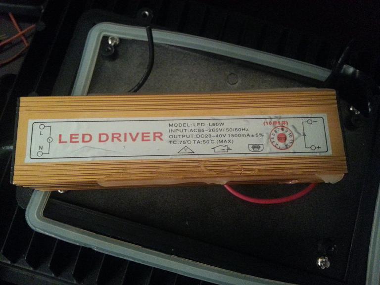
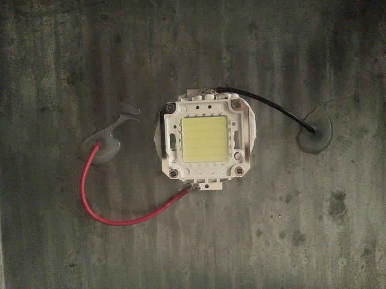
So I'm trying to dim this LED (see attached pics).
I have the circuit set up as illustrated but the LED doesn't fade. The driver makes a loud buzzing noise when using anything under 255 with PWM, but the light output stays about the same. I've tried a 220ohm and 1kohm resistor on the base with the same results.
Here is the code I'm using to test, but I'm sure this is a hardware issue.
This same circuit worked fine on a LED strip that I have.
Any suggestions?
Thanks,
-Raul
int ledone = 9;  // the pin that the LED is attached to
int brightness = 55;    // how bright the LED is
int fadeAmount = 1;    // how many points to fade the LED by


void setup()  {

  pinMode(ledone, OUTPUT);

}

// the loop routine runs over and over again forever:
void loop()  {

  // set the brightness of pin 9:
  analogWrite(ledone, brightness);

  // change the brightness for next time through the loop:
  brightness = brightness + fadeAmount;

if (brightness == 255){
  delay(5000);
}


  // reverse the direction of the fading at the ends of the fade:
  if (brightness == 55 || brightness == 255) {
    fadeAmount = -fadeAmount ;
  }
  // wait for 30 milliseconds to see the dimming effect
  delay(100);
    }
All I can think of is the transistor is under full saturation, I'd stick 10k on the base of the transistor and try.
I thought I would want the transistor fully saturated because of the high current its pulling?
Wouldn't putting a 10k cause the transistor to overheat?
I've also ruled out all the individual components as I have doubles and triples of everything.
In my opinion, your load is not the led. Your load is the led driver with the led connected normally.
Do you have access to a 10A Solid State Relay that is designed for switching AC loads (there are two types : AC & DC, you have to make sure the relay says AC on it) ? When you switch the transistor that is sinking the led current , you are altering the load impedance of the led driver load. It is designed to switch the led full on or full off. The maximum power transfer theorem states the maximum power is transferred when the load matches the source. By switching the led the driver is seeing LOAD/NO LOAD/LOAD /NO LOAD and it is not designed to operate in that manner. You must connect the led the way it is designed to operate and try switching the led driver with an AC solid state relay . It has a zero crossing detector in it so it only switches when the ac waveform is at zero , thus never switching under power. The PWM pin of the arduino is connected to the dc input pins of the SSR which turn on with any dc voltage between 3 V and 36V. The AC HOT lead of the led driver is cut and the two ends connected to the AC terminals of the SSR. The SSR will function like an SPST switch with one major difference. It is a "SMART" SPST switch that only turns on or off at ac zero crossing. If the dc voltage on the input changes from HIGH to LOW, nothing happens on the AC OUTPUT terminals until the ac waveform crosses zero and then the output is switched OFF.Conversely if the input changes from LOW to HIGH, the load is not switched off until the waveform reaches zero crossing point. This means the shortest period of time that it can be on is one half cycle or 8.3 mS. If you look at the ac waveform on a scope while changing the PWM pin output from 0 to 255, what you see is entire cycles disappearing during the LOW state of the PWM. Since it is not an AC PHASE controller, the best it can do is turn on for a number of ac cycles that comes closest to the ON TIME of the duty cycle of the PWM, +/- one half cycle. When you watch an incandescent light bulb being swiched with a solid state relay, it does not "dim" like a standard wall dimmer knob you can buy at the hardware store. Instead it flickers , because it is not phase controlling. For this reason, a solid state relay may not work for your application. What you really need is either a variac or a TRIAC phase controller which can switch the ac on or off at any point in the wave form. These are usually called "choppers". I have never built one but if I had the parts and a schematic it would be straight forward. Why do you wantto dim a 50W led and HOW do you want to dim it ? (meaning duty cycle from 0 to 255 in how many mS ? (response time spec)
I want to do this for my reef tank. I have 3 50w leds on the tank. I want them to fade up gradually for one hour, stay on for about 7 hours then fade to off over the next hour to simulate a sunrise/set.
I'm not opposed to replacing the driver if necessary.
Does anyone know of any drivers with similar specs that accept PWM?
I don't know if a solid state relay will work. It's possible the only thing thst will work is a Triac phase controller. With no information on
the led driver I just don't know.
raschemmel:
In my opinion, your load is not the led. Your load is the led driver with the led connected normally.
Do you have access to a 10A Solid State Relay that is designed for switching AC loads (there are two types : AC & DC, you have to make sure the relay says AC on it) ?
But the output on the transformer says DC...
A regular power transistor or fet, should do the job, The only thing i'd maybe change is running the PWM through a low pass filter before passing it to it's base.
another option might be to get hold of a 12v - 19v laptop power supply greater than 50watts, and then Step the voltage up if you can't find a high enough rated power supply.
raschemmel:
I don't know if a solid state relay will work. It's possible the only thing thst will work is a Triac phase controller. With no information on
the led driver I just don't know.
Hi, the LED driver you have is not designed to have its load PWM modulated as has already been said.
Putting a SCR type control on the 110Vac Input will not work, as the driver is a switched mode power supply, usually running in constant current mode, not a simple transformer/rectifier unit.
To fix your problem you will probably need to get a LED driver with a dimmer input.
Try here.
Have you tried to run the led on a MOSFET with any other power supply? Some printers have very large powersupplys that may have your voltage and current rating. But when running a lot of larger DC loads (motors large LEDs sensors and such) I like to build a power supply for the job at hand. You should be able to get a transformer down to your LEDs voltage then rectify to DC use a large cap on the DC side to stabilize it and it should work great with a MOSFET switch and pwm.