Hi guys, I'm working on a project: it's about an automaton which already have sensors but when there is 1 of 5 issues, only a LED start winking. So the technician lose a lot of time trying to find the issue.
I thought on a solution: connecting an arduino directly on the inputs of the automaton which are connected to sensors and then connect an LCD who will display an error message.
The thing is, the automaton operates with 24V, and the Arduino Uno allows only 5V. I think that a static relay or even only optocouplers can be enough, what do you think?
Thanks in advance.
How is the Arduino going to interpret the blinking LED to get an error? Connecting the Arduino's input to the automaton (?) is going to help how?
Please provide more information so we can understand the goal and issues.
More specific to your question: yes, it is always a good idea to interconnect machines over which you do not have complete control via optocouplers - but you still need to know enough about that other machine even to achieve this. And 24v as a power source can still be converted low enough for the Arduino via a simple step-down converter, that is the easiest part of the project.
Actually each sensor is viewed as an input in the automaton and the led is an output. Instead of focusing in the led I'm focusing on the automaton terminal where each sensor deliver 24 V when it's on and 0 when nothing received.
Meneboys:
...each sensor deliver 24 V when it's on and 0 when nothing received.
So is the presence of zero volts on a sensor output the error you want to detect?
Exactly, but not directly on the sensor but throught the automate which deliver 24V
A potential divider should do the trick.
You want 1/5th of the voltage so a 1k and 3.9k resistor between the 24v and ground with the Arduino at the junction of these resistors. (3.9k to the 24v and 1k between that and ground).
For safety, I would also include a 5.1v zener diode (between the 1k and ground) as I would not trust the automaton's voltage. Possible 4.7v even.
Additionally I would triple check the voltages with a voltmeter before connecting anything to my Arduino.
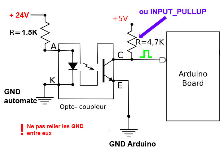
As a safer alternative you could use optocouplers as long as you can get 5mA or so from that sensor. You would have to read the datasheet to find out the forward voltage of the opto-coupler's LED to work out the resistor values.
Example: your optocoupler LED requires 4mA with a forward voltage drop of 2.1v. Therefore you need to drop 21.9v at 4mA so that's 5.5K - nearest preferred value would be 5.6K.
Any of this make sense?
I prefer the solution of an opto coupler so a friend of mine draw me this scheme but since I'm a newbie I can't say how he choose the resistors values. Does he just calculate it with for exemple the input/output voltage and the max current we can put in the optocoupler and the max current the arduino allows? Or should I measure the current that comes with the 24V? Thanks in advance