Display RPM on LCD_I2C of 2 DC motors with encoder on shaft

Hi everyone,

I am new to mechatronics and I am building a 2WD car which can be controlled with a XY-axis joystick. Currently everything works.

BOM:

  • Ardunio UNO
  • L298N H-Bridge
  • LCD with I2C module
  • Simple XY-Axis joystick
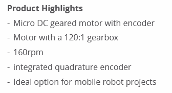
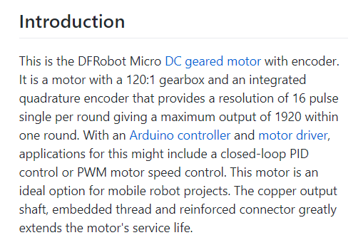
  • 2x DC motors geared with Encoder on the shaft (see picture below)

Connections are all good. The car is moving as it should move.

The question here is, how can i display the RPM (Speed) on the display using these encoders on the motors?

I have connected the pins from the encoder like on the picture below (for both motors on pin 2 and ~3 of the arduino.

CODE

#define enA 9
#define in1 4
#define in2 5
#define enB 10
#define in3 6
#define in4 7

// Library voor de LCD met I2C module (deze module zorgt er voor dat je maar 4 jumperkabels nodig hebt ipv 8)
#include <Wire.h>
#include <LiquidCrystal_I2C.h>

LiquidCrystal_I2C lcd(0x27,16,2);

int motorSpeedA = 0;
int motorSpeedB = 0;

void setup() {
  pinMode(enA, OUTPUT);
  pinMode(enB, OUTPUT);
  pinMode(in1, OUTPUT);
  pinMode(in2, OUTPUT);
  pinMode(in3, OUTPUT);
  pinMode(in4, OUTPUT);

  // Initialiseren LCD scherm
  lcd.init();
  lcd.init();

  // Display een bericht op de LCD
  lcd.backlight();
  lcd.setCursor(1,0);
  lcd.print("MR.BEAN");
  lcd.setCursor(1,1);
  lcd.print("ROBOT AUTO");
}

void loop() {
  int xAxis = analogRead(A0); // Read Joysticks X-axis
  int yAxis = analogRead(A1); // Read Joysticks Y-axis

  // Y-axis used for forward and backward control
  if (yAxis < 470) {
    // Set Motor A backward
    digitalWrite(in1, HIGH);
    digitalWrite(in2, LOW);
    // Set Motor B backward
    digitalWrite(in3, HIGH);
    digitalWrite(in4, LOW);
    // Convert the declining Y-axis readings for going backward from 470 to 0 into 0 to 255 value for the PWM signal for increasing the motor speed
    motorSpeedA = map(yAxis, 470, 0, 0, 255);
    motorSpeedB = map(yAxis, 470, 0, 0, 255);
  }
  else if (yAxis > 550) {
    // Set Motor A forward
    digitalWrite(in1, LOW);
    digitalWrite(in2, HIGH);
    // Set Motor B forward
    digitalWrite(in3, LOW);
    digitalWrite(in4, HIGH);
    // Convert the increasing Y-axis readings for going forward from 550 to 1023 into 0 to 255 value for the PWM signal for increasing the motor speed
    motorSpeedA = map(yAxis, 550, 1023, 0, 255);
    motorSpeedB = map(yAxis, 550, 1023, 0, 255);
  }
  // If joystick stays in middle the motors are not moving
  else {
    motorSpeedA = 0;
    motorSpeedB = 0;
  }

  // X-axis used for left and right control
  if (xAxis < 470) {
    // Convert the declining X-axis readings from 470 to 0 into increasing 0 to 255 value
    int xMapped = map(xAxis, 470, 0, 0, 255);
    // Move to left - decrease left motor speed, increase right motor speed
    motorSpeedA = motorSpeedA - xMapped;
    motorSpeedB = motorSpeedB + xMapped;
    // Confine the range from 0 to 255
    if (motorSpeedA < 0) {
      motorSpeedA = 0;
    }
    if (motorSpeedB > 255) {
      motorSpeedB = 255;
    }
  }
  if (xAxis > 550) {
    // Convert the increasing X-axis readings from 550 to 1023 into 0 to 255 value
    int xMapped = map(xAxis, 550, 1023, 0, 255);
    // Move right - decrease right motor speed, increase left motor speed
    motorSpeedA = motorSpeedA + xMapped;
    motorSpeedB = motorSpeedB - xMapped;
    // Confine the range from 0 to 255
    if (motorSpeedA > 255) {
      motorSpeedA = 255;
    }
    if (motorSpeedB < 0) {
      motorSpeedB = 0;
    }
  }
  // Prevent buzzing at low speeds (Adjust according to your motors. My motors couldn't start moving if PWM value was below value of 70)
  if (motorSpeedA < 70) {
    motorSpeedA = 0;
  }
  if (motorSpeedB < 70) {
    motorSpeedB = 0;
  }
  analogWrite(enA, motorSpeedA); // Send PWM signal to motor A
  analogWrite(enB, motorSpeedB); // Send PWM signal to motor B
}

Quick glance and I don't see any inputs in your code...

You show wiring for one encoder (Pin 2 and 3). Where is the other encoder connected?

To measure RPM you need to measure how long it takes to move a measured number of steps (good for high speeds) or how many steps you take in a measured amount of time (better for low speeds). There are encoder libraries for measuring steps and millis() for measuring time.

I have them both connected to 2-3 since they are the only interrupt 0-1.

Have you any suggestion on how to implement this? Which library can i use? I am totally lost.. So far i have only connected the encoders, dont even know how to check them.

You can't connect both wires from both encoders to the same two pins. They will interfere with each other.

Here are two. Try one. If it doesn't work for you, try the other one.

Alright,

I have tried without library. The problem now is when i turn left or right, one motorspeed = 0, but the RPM rises up to 3000-6000..... But going forward or backward it works (2x ±160 RPM).

See code below.


#define enA 9
#define in1 4
#define in2 5
#define enB 10
#define in3 6
#define in4 7
#define ENC_COUNT_REV 3790

#define ENC_IN 3

#define PWM 2
#define DIR 3

int speedcontrol = 0;
volatile long encoderValue = 0;
int interval = 1000; 
long previousMillis = 0;
long currentMillis = 0;
int rpm = 0;
int motorPwm = 0;

// Library voor de LCD met I2C module (deze module zorgt er voor dat je maar 4 jumperkabels nodig hebt ipv 8)
#include <Wire.h>
#include <LiquidCrystal_I2C.h>

LiquidCrystal_I2C lcd(0x27,16,2);

int motorSpeedA = 0;
int motorSpeedB = 0;

void setup() {

  Serial.begin(9600);
  pinMode(ENC_IN, INPUT_PULLUP);

  pinMode(PWM, OUTPUT);
  pinMode(DIR, OUTPUT);
  attachInterrupt(digitalPinToInterrupt(ENC_IN) ,updateEncoder, RISING);
  previousMillis = millis();
  
  pinMode(enA, OUTPUT);
  pinMode(enB, OUTPUT);
  pinMode(in1, OUTPUT);
  pinMode(in2, OUTPUT);
  pinMode(in3, OUTPUT);
  pinMode(in4, OUTPUT);

  // Initialiseren LCD scherm
  lcd.init();
  lcd.init();

 
}

void loop() {

  
  int xAxis = analogRead(A0); // Read Joysticks X-axis
  int yAxis = analogRead(A1); // Read Joysticks Y-axis

  
  // Y-axis used for forward and backward control
  if (yAxis < 470) {
    // Set Motor A backward
    digitalWrite(in1, HIGH);
    digitalWrite(in2, LOW);
    // Set Motor B backward
    digitalWrite(in3, HIGH);
    digitalWrite(in4, LOW);
    // Convert the declining Y-axis readings for going backward from 470 to 0 into 0 to 255 value for the PWM signal for increasing the motor speed
    motorSpeedA = map(yAxis, 470, 0, 0, 255);
    motorSpeedB = map(yAxis, 470, 0, 0, 255);
  }
  else if (yAxis > 550) {
    // Set Motor A forward
    digitalWrite(in1, LOW);
    digitalWrite(in2, HIGH);
    // Set Motor B forward
    digitalWrite(in3, LOW);
    digitalWrite(in4, HIGH);
    // Convert the increasing Y-axis readings for going forward from 550 to 1023 into 0 to 255 value for the PWM signal for increasing the motor speed
    motorSpeedA = map(yAxis, 550, 1023, 0, 255);
    motorSpeedB = map(yAxis, 550, 1023, 0, 255);
  }
  // If joystick stays in middle the motors are not moving
  else {
    motorSpeedA = 0;
    motorSpeedB = 0;
  }

  // X-axis used for left and right control
  if (xAxis < 470) {
    // Convert the declining X-axis readings from 470 to 0 into increasing 0 to 255 value
    int xMapped = map(xAxis, 470, 0, 0, 255);
    // Move to left - decrease left motor speed, increase right motor speed
    motorSpeedA = motorSpeedA - xMapped;
    motorSpeedB = motorSpeedB + xMapped;
    // Confine the range from 0 to 255
    if (motorSpeedA < 0) {
      motorSpeedA = 0;
    }
    if (motorSpeedB > 255) {
      motorSpeedB = 255;
    }
  }
  if (xAxis > 550) {
    // Convert the increasing X-axis readings from 550 to 1023 into 0 to 255 value
    int xMapped = map(xAxis, 550, 1023, 0, 255);
    // Move right - decrease right motor speed, increase left motor speed
    motorSpeedA = motorSpeedA + xMapped;
    motorSpeedB = motorSpeedB - xMapped;
    // Confine the range from 0 to 255
    if (motorSpeedA > 255) {
      motorSpeedA = 255;
    }
    if (motorSpeedB < 0) {
      motorSpeedB = 0;
    }
  }
  // Prevent buzzing at low speeds (Adjust according to your motors. My motors couldn't start moving if PWM value was below value of 70)
  if (motorSpeedA < 70) {
    motorSpeedA = 0;
  }
  if (motorSpeedB < 70) {
    motorSpeedB = 0;
  }
  analogWrite(enA, motorSpeedA); // Send PWM signal to motor A
  analogWrite(enB, motorSpeedB); // Send PWM signal to motor B
  
  // Control motor with potentiometer
    motorPwm = map(analogRead(speedcontrol), 0, 1023, 0, 255);
    
    // Write PWM to controller
    analogWrite(PWM, motorPwm);
  
  // Update RPM value every second
  currentMillis = millis();
  if (currentMillis - previousMillis > interval) {
    previousMillis = currentMillis;


    // Calculate RPM
    rpm = (float)(encoderValue * 60 / ENC_COUNT_REV);

    // Only update display when there is a reading
    if (motorPwm > 0 || rpm > 0) {
      Serial.print("PWM VALUE: ");
      Serial.print(motorPwm);
      Serial.print('\t');
      Serial.print(" PULSES: ");
      Serial.print(encoderValue);
      Serial.print('\t');
      Serial.print(" SPEED: ");
      Serial.print(rpm);
      Serial.println(" RPM");

       // Display een bericht op de LCD
  lcd.backlight();
  lcd.setCursor(1,0);
  lcd.print("PWM: ");
  lcd.print(motorPwm);
  lcd.print(" t");
  lcd.setCursor(1,1);
  lcd.print("SPEED: ");
  lcd.print(rpm);
  lcd.print(" RPM");
    }
    
    encoderValue = 0;
  }
}

void updateEncoder()
{
  encoderValue++;
}

Post a schematic of the new wiring, please.

The Encoder library allows you to use 1 interrupt pin and 1 regular pin for each encoder.

Havent change wiring.

Both encoders are connected to pins 2 and 3. Dont know which i should use otherwise for the 2nd encoder

It looks like each motor has a quadrature encoder. With a quadrature encoder's 2 outputs you are able to measure speed and rotational direction. If you only want to measure rotational speed of each motor, you only need 1 output from each encoder. Connect one of one motor's encoder output to pin 2 and one of the other motor's outputs to pin 3. Attach an interrupt for each pin and make an ISR for each pin (2 and 3) to count the pulses versus time. Then you can calculate the RPM.

If as @groundFungus is correct and your encoders are quadrature encoders. They will provide many pulses for each revolution. To calculate speed you will have to know how many pulses will occur in one revolution.
Perhaps the motor's spec will say, or you could count them if you can turn the shaft manually.

These are the specs of the DC motors:
I have tried couple of codes to read the pulse for one rotation. Should i get around 320 RPM?

afbeelding

Do you have a data sheet or manual for the motor showing the encoder connections?

It looks to me that the encoder is connected right to the motor shaft so should be in the thousands of RPM with no load.

Do you have a simple code that just gets pulses from the encoder?

I used the following code to determine the pulse:

 /*     Arduino Rotary Encoder Tutorial
 *      
 *  by Dejan Nedelkovski, www.HowToMechatronics.com
 *  
 */
 
 #define ENC_IN2 2
 #define ENC_IN4 3

 int counter = 0; 
 int aState;
 int aLastState;
 int A_encoderValue = 0;
 int B_encoderValue = 0;  

 void setup() { 
   pinMode (ENC_IN2,INPUT_PULLUP);
   pinMode (ENC_IN4,INPUT_PULLUP);
   
   Serial.begin (9600);
   // Reads the initial state of the outputA
   aLastState = digitalRead(ENC_IN2); 
  attachInterrupt(digitalPinToInterrupt(ENC_IN2), A_updateEncoder, RISING);
  attachInterrupt(digitalPinToInterrupt(ENC_IN4), B_updateEncoder, RISING);  
 } 

 void loop() { 
   aState = digitalRead(ENC_IN2); // Reads the "current" state of the outputA
   // If the previous and the current state of the outputA are different, that means a Pulse has occured
   if (aState != aLastState){     
     // If the outputB state is different to the outputA state, that means the encoder is rotating clockwise
     if (digitalRead(ENC_IN4) != aState) { 
       counter ++;
     } else {
       counter --;
     }
     Serial.print("Position: ");
     Serial.println(counter);
   } 
   aLastState = aState; // Updates the previous state of the outputA with the current state
 }

 void A_updateEncoder()
{
  // Increment value for each pulse from encoder
  A_encoderValue++;
}

void B_updateEncoder()
{
  // Increment value for each pulse from encoder
  B_encoderValue++;
}

I think this is the datasheet of the encoder:

This doesn't look like your typical quadrature encoder, however it will allow you to measure RPM. Its a magnetic low resolution type.

Its stated each output outputs 16 pulses/revolution. And if the goal is to measure the output shaft RPM then you would have to divide the received pulses by 120.

image

Im totally new to this and learned a bunch in 24h.

I have counted the rpm manually and counted approx 88 rates per minute (full speed). Also i have tried to connect just one motor with a L298N driver and arduino with a potentiometer. PWM signal display is 253. But now im just guessing the pulse to get closer to 88 rpm. Am i doing that right? Have no idea if im guessing the right way.

Why don't you try the code on the motor page? It would seem a good place to start. It prints the rpm to the IDE serial monitor.

You mean the 2nd one? Wasnt that far yet. The 2nd one keeps the rpm steady at 80. The first one ive tried, but gives different pulses.

I was thinking of Sample 1 on this link

This topic was automatically closed 180 days after the last reply. New replies are no longer allowed.