Distributing power to many at once servos

Hello!

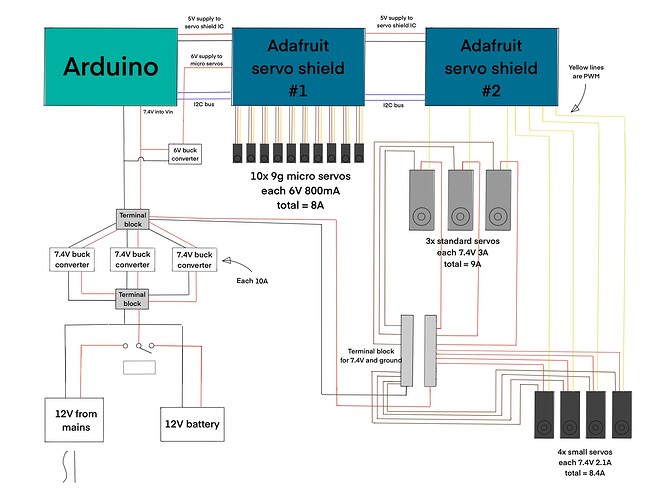
I'm building a robot that contains a variety of different servos. I'm using an Arduino Uno R3 and two Adafruit servo shields (Adafruit 16-channel PWM/Servo Shield). The shields rely on I2C communication and the ICs on them rely on voltage provided by the Arduino, whereas the servos connected to them rely on dedicated power that is also fed into the shields separately.

It occurred to me that with so many high-amperage servos, the shields might not be able to safely handle all that current, so I figured that with the big servos, I would power them separately while leaving their PWM pins connected to the shields.

I've never had to distribute power to a project of this complexity before. I'm quite new to it, so I was wondering if anyone could comment on the setup I've devised:


In my design I am using a total of 20 servos (there would actually be closer to 24 in the final build, but this is a start). I've labelled the operating voltage and maximum current of each servo in the diagram.

I was thinking that I would like to be able to switch between wall power and batter power, so I figured I could place a switch to select between the positive leads of each power source. If this design is flawed, please let me know.

A big issue is making sure that the correct voltages reach each component: 6V for Arduino and micro-servos, 7.4V for larger servos. My research has told me that voltage regulators (perhaps linear or perhaps bucks) would be the way to go here. I would allow the micro servos to be powered through the shield (each shield has a dedicated servo power input, albeit not with that much current allowed), and only connect the PWM leads of the larger servos to the second shield, connecting their positive and ground pins to a dedicated terminal block, which is itself connected to the 7.4V regulator.

Does this all sound sensible? This is my first time doing this, and it's taken me quite a bit of research to figure out how to power so many components. I would also appreciate feedback if anyone has a simpler or more efficient way of accomplishing this configuration of servos. I know for instance that linear voltage regulators can be a bit inefficient. I wrote "12V" for the power sources because it's hard to find power supplies with any less voltage than that but with enough current for all these parts.

Lastly, this design, which looks like it requires about 30 amps of current, is probably a bit overkill. I can all but guarantee that there would never be a point where all 20 servos are running at full power at the same time, but I can't say that it would never get close to that, so I want to be prepared.

Any feedback is appreciated. Thanks!

Buck converters are best, because they loose less power. A liner regulator simply burns off the excess power as heat.

The Adafruit servo shield output FETs can't supply that amount of current, so you need to rethink the driver requirements from that. See the data sheet of the chip it uses for the complete solutions.
See:-
PCA9685.pdf

You also need to consider power supply decoupling thought the system.

See my tutorial at:-

What pin is used in your diagram to power the Uno? A schematic would have been better. In a schematic, every pin (that is used) is labelled.

If you plan to use the 5V pin on the Uno, 6V will damage it.

If you plan to use the Vin pin, 6V is too low. Use the 7.4V supply.

I would not recommend chaining your voltage regulators like that (meaning feed 7.4V into the 6V regulator). It doesn't make them more efficient and risks overloading the 7.4V regulator. I agree with @Grumpy_Mike that DC-DC voltage "buck" converters would be more appropriate, being more efficient and less prone to overheating.

I'm not sure what FETs @Grumpy_Mike is referring to here, unless it's the output driver FETs inside the PCA chip. But those are only providing PWM signals, which I would have expected to be very low current.

Yes those are the ones.

It is explained on page 29 of the data sheet.

The PCA9685 LED output drivers are 5.5 V only tolerant and can sink up to 25 mA at 5 V.

You will see from the schematic of the Adafruit board that there are no external FETs.
Servo shield schematic

But remember those will just be PWM signals designed to trigger the servos, and not to power them.

Exactly. So what's the reason for the re-think? What amount of current will these pins be expected to handle?

I don't see where the servos ground (signal return) is connected to shield #2.

Thank you all for these thoughts! I've made some modifications to my diagram:


I am now using buck converters instead of linear regulators. I've also specified 7.4V going into the Arduino's Vin pin.

One probably strange modification is that I'm splitting the power after it comes from the source (wall or battery) into three identical buck converters and then putting it back together again. The reason I did this was because, upon my first attempt to search for one, it's rather difficult to find buck converters that can handle up to 30 amps of current. It's much easier to find ones that can handle 10 amps. I would hope that this configuration solves that problem by letting each converter handle 1/3 of the current load. Recombining them, I would then have the output go into the Arduino as well as a second 6V buck converter to power the micro servos. Please let me know if this method is flawed, or if there are in-fact single-board converters that can do this job.

To address @Grumpy_Mike , I agree that the shield probably can't handle that much current. I might have to have a separate terminal block (I've also found a nifty servo power distribution board from GoBilda) for them. As for power supply decoupling, I looked at your tutorial but I didn't include it in my new diagram because I haven't taken the time yet to carefully consider the exact capacitors/inductors that would be necessary. I wish you could provide a specific guide to choosing these components for a given circuit, but as you say, it may be more art than science.

To reply to @JCA34F , the shield #2 servos are connected to ground via the terminal block, which shares a common ground with all other components, including the shields via the Arduino (black line toward the top of the diagram). I could have connected the servos ground back up to the shield as well, but I think that would have created a ground loop (correct me if I'm wrong).

Basically all the small ceramic capacitors should be 0.1uF.

It is the electrolytes that should be increased as the current is larger. With your circuit I would start with 1000uF and keep on doubling until it starts to work without a problem.

Because a 5V signal might be fine for a 6V servo, you have to watch it with higher voltage servos to see if it will trigger the signal input. You might need a bit of level shifting going on.

1 Like

This topic was automatically closed 180 days after the last reply. New replies are no longer allowed.