DIY :: Coolant Temperature Gauge for Motorcycles

Hi,

I am new to arduino forum. I am basically a website designer, got lots of interest in electronics too. I got a Yamaha R15v2.0 2016 Indian Version. Since my motorcycle was flooded due to heavy rain, the radiator system doesn't works at all. So, I took my bike to service center they said that, i have to change total wiring and ECU board. It will cost around 12,000. That's too cost. So i planned to make it work on my own. So after a lots of googling i find that arduino is the best solution. So friends, please help me to make an arduino powered coolant radiator system for my motorcycle(auto-drive radiator fan ON and OFF, a small temperature gauge using "10 segment led bar graph").

  1. My coolant temperature sensor is fine.

  1. My Radiator Fan and Relay is Fine.

  2. Engine Coolant Circulation is also fine.


I bought a new arduino UNO board. Have to start working on it. Since C++ coding is familiar to me it is easy to understand some basic arduino code's too.


Using a Multi-meter, I started plotting the resistance value of the coolant temperature sensor. I find out that in 80 degree Celsius, the thermostat starts allowing the coolant from the engine's head to pass through the radiator fins. So at that time, the radiator fan should start. So that it can cool down the coolant oil passing through the radiator fins. At 80 degree Celsius the resistance of the coolant temperature sensor is 340 Ohms. So according to the calculations, the radiator fan should start working when the sensor reaches 340 Ohms, and continue running for next 10 mins.


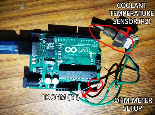
I also read that resistance can be measure using arduino using "arduino ohmmeter program"

In the above image i connected the coolant temperature sensor to the "unknown resistor" pins and now I am able to get the resistance results in my serial monitor.

The code I got

int analogPin= 0;
int raw= 0;
int Vin= 5;
float Vout= 0;
float R1= 1000;
float R2= 0;
float buffer= 0;

void setup()
{
Serial.begin(9600);
pinMode(LED_BUILTIN, OUTPUT);
}

void loop()
{
raw= analogRead(analogPin);
if(raw) 
{
buffer= raw * Vin;
Vout= (buffer)/1024.0;
buffer= (Vin/Vout) -1;
R2= R1 * buffer;

Serial.print("Resiatance: ");
Serial.println(R2);
delay(1000);

}
}

Have to modify the above code to make Pin-13 high for 10 mins when the resistance reaches 340 Ohms.

Help me with that coding friends. Also have to make the 10 segment led bar-graph to show the level of heat in the engine coolant oil.

The Readings are as follows,

So now the query,

at 35 deg - first bar should light up
at 40 deg - first bar + second bar
at 45 deg - first bar + second bar + third bar
50 - first bar + second bar + third bar + fourth bar
60 - first bar + second bar + third bar + fourth bar + fifth bar
70 - first bar + second bar + third bar + fourth bar + fifth bar + sixth bar
80 - first bar + second bar + third bar + fourth bar + fifth bar + sixth bar + seventh bar
90 - first bar + second bar + third bar + fourth bar + fifth bar + sixth bar + seventh bar +eighth bar
100 -first bar + second bar + third bar + fourth bar + fifth bar + sixth bar + seventh bar +eighth bar+ ninenth bar

  • From 1st bar till 9th bar "no blink".

  • 10th bar should blink when the radiator fan starts, as like notification still it stops.

As the temperature decreases the led also decreases on by one as i quoted above.


Thank you Friends.

Will post images soon, as i start working.... :slight_smile:

You'll need a MOSFET, transistor, or relay to drive the fan. Do you know how much current (amps) it takes?

For the software, you only need to learn a couple of things...

You'll need some [u]if-statments[/u]. (If temperature is > X, turn-on an LED... If temperature > Y, turn on an LED and the fan...)

As a "first pass" to get your program working you can use delay() to turn-on the fan for 10 minutes (600,000 milliseconds).

For testing & debugging purposes you'll want to shorten that time. And speaking of testing & debugging, get a 10K pot (potentiometer) so you can simulate the temperature sensor.

The problem with delay() is that your program pauses during the delay time. That's no good because you want to continue reading the temperature and updating the LED display while the fan is running. So, look at the [u]Blink Without Delay Example[/u]. Also, look at the post at the top of the forum about Demonstration Code for Several Things At The Same Time.

DVDdoug:
You'll need a MOSFET, transistor, or relay to drive the fan. Do you know how much current (amps) it takes?

Yeah i got a 5v Relay to drive the Radiator Fan. The relay can handle a maximum of 10A @ 120V or 7A @ 240V AC, 7A/24V DC. So i think this relay is enough to drive the fan.

DVDdoug:
For the software, you only need to learn a couple of things...

You'll need some [u]if-statments[/u]. (If temperature is > X, turn-on an LED... If temperature > Y, turn on an LED and the fan...)

As a "first pass" to get your program working you can use delay() to turn-on the fan for 10 minutes (600,000 milliseconds).

I got a very good idea like how to use the if statement to do my job, one thing that hurts is the delay() function... as you mentioned the whole arduino gets pause while delay() is activating for 10 minutes.

DVDdoug:
The problem with delay() is that your program pauses during the delay time. That's no good because you want to continue reading the temperature and updating the LED display while the fan is running. So, look at the [u]Blink Without Delay Example[/u]. Also, look at the post at the top of the forum about Demonstration Code for Several Things At The Same Time.

Still now i am not getting anything about "delay without blink" function, but i will in sometimes i think LOL. I will post the code soon.

Given the thermistor table above, you'll need to measure its resistance to determine the temperature.

I suggest the enclosed circuit.

Now plot the a/d value you get against temperature to determine your actions...........

I'd use excel for this.

The value you get by reading the analog input is : 1023 * thermistor value/(thermistor val +1k)

Allan

mcoil.pdf (17 KB)

pradoartz:
At 80 degree Celsius the resistance of the coolant temperature sensor is 340 Ohms. So according to the calculations, the radiator fan should start working when the sensor reaches 340 Ohms, and continue running for next 10 mins.

What calculations?

To run the display

Allan

Is that an answer to reply #4? If so, it might be better answered by somebody with the Yamaha service manual to hand.

If you read the OP's first post, he also wants an LED bargraph temperature gauge, which could be driven by the thermistor's resistance..

Allan

allanhurst:
wants an LED bargraph temperature gauge

A separate issue, and not what I quoted from the OP.

pradoartz:
Yeah i got a 5v Relay to drive the Radiator Fan. The relay can handle a maximum of 10A @ 120V or 7A @ 240V AC, 7A/24V DC. So i think this relay is enough to drive the fan.

The fact that the coil may be 5V is fine, but how much current does the coil draw?
What is its resistance, can you post a link to the data/specs of the relay please?
You may need a transistor to switch the coil current.
Tom... :slight_smile:

Nick_Pyner:
What calculations?

  • According to the Yamaha service manual, when the bike reaches 80 degree Celsius, the radiator fan should start working and it stops after 10 minutes.

  • The sensor gives the OP as 340 ohms when the bike reaches 80 degree Celsius.

  • So have to build a voltage divider circuit using arduino to find the OP resistance from the temperature sensor, and to use the OP to start the radiator fan.

if(R2 <= 340) // R2 is the OP from temperature sensor
{
digitalWrite(ledPin, HIGH); // Pin 13 to high, so if i connect a 5v relay to pin 13, it should turn on the relay
delay(600000); // Relay On for 10 minutes
digitalWrite(ledPin, LOW) // Relay Off after 10 minutes
}

allanhurst:
Given the thermistor table above, you'll need to measure its resistance to determine the temperature.

I suggest the enclosed circuit.

Now plot the a/d value you get against temperature to determine your actions...........

I'd use excel for this.

The value you get by reading the analog input is : 1023 * thermistor value/(thermistor val +1k)

Allan

Hello Allan thanks for the information,
As I don't want to calculate the temperature, instead of the temperature we can use the OP resistance from temperature sensor. Any ways each temperature got its own resistance value from the sensor.

TomGeorge:
The fact that the coil may be 5V is fine, but how much current does the coil draw?
What is its resistance, can you post a link to the data/specs of the relay please?
You may need a transistor to switch the coil current.
Tom... :slight_smile:

The relay which i used is ---> http://www.electroncomponents.com/1-Channel-Relay-Board-5v?filter_name=%205%20v%20relay

And if i want to use a transistor to kick the relay to ON means, whats the circuit and components should i use. I don't have much knowledge in transistors bro.

Thanks..

I got LED Bar-graph code from one website and altered a little to suit my query,

//declares all the pin connections to the arduino board
const int LED1= 11; 
const int LED2= 10;
const int LED3= 9;
const int LED4= 8;
const int LED5= 7;
const int LED6= 6;
const int LED7= 5;
const int LED8= 4;
const int LED9= 3;
const int LED10= 2;
const int potentiometer= A0;

int value=0;

//declares the LEDs as outputs and the potentiometer as inputs
//also creates a Serial Monitor so that we can see what the actually analog value is
void setup()
{
pinMode(LED1, OUTPUT); 
pinMode(LED2, OUTPUT);
pinMode(LED3, OUTPUT);
pinMode(LED4, OUTPUT);
pinMode (LED5, OUTPUT);
pinMode (LED6, OUTPUT);
pinMode (LED7, OUTPUT);
pinMode (LED8, OUTPUT);
pinMode (LED9, OUTPUT);
pinMode (LED10, OUTPUT);
pinMode (potentiometer, INPUT);
Serial.begin(9600);
}

void loop()
{
value= analogRead(potentiometer);
Serial.println(value);

//at 35 degrees
if ((value >= 1802) && (value < 9420))
{
digitalWrite (LED1, HIGH);
digitalWrite (LED2, LOW);
digitalWrite (LED3, LOW);
digitalWrite (LED4, LOW);
digitalWrite (LED5, LOW);
digitalWrite (LED6, LOW); 
digitalWrite (LED7, LOW);
digitalWrite (LED8, LOW); 
digitalWrite (LED9, LOW);
digitalWrite (LED10, LOW); 
}

//at 40 degrees
if ((value >=1459) && (value < 1802))
{
digitalWrite (LED1, HIGH);
digitalWrite (LED2, HIGH);
digitalWrite (LED3, LOW);
digitalWrite (LED4, LOW); 
digitalWrite (LED5, LOW);
digitalWrite (LED6, LOW); 
digitalWrite (LED7, LOW);
digitalWrite (LED8, LOW); 
digitalWrite (LED9, LOW);
digitalWrite (LED10, LOW); 
}

//at 45 degrees
if ((value >= 1188) && (value < 1459))
{
digitalWrite (LED1, HIGH);
digitalWrite (LED2, HIGH);
digitalWrite (LED3, HIGH);
digitalWrite (LED4, LOW); 
digitalWrite (LED5, LOW);
digitalWrite (LED6, LOW); 
digitalWrite (LED7, LOW);
digitalWrite (LED8, LOW); 
digitalWrite (LED9, LOW);
digitalWrite (LED10, LOW); 
}

//at 50 degrees
if ((value >= 973) && (value < 1188))
{
digitalWrite (LED1, HIGH);
digitalWrite (LED2, HIGH);
digitalWrite (LED3, HIGH);
digitalWrite (LED4, HIGH); 
digitalWrite (LED5, LOW);
digitalWrite (LED6, LOW); 
digitalWrite (LED7, LOW);
digitalWrite (LED8, LOW); 
digitalWrite (LED9, LOW);
digitalWrite (LED10, LOW); 
}

//at 60 degrees
if ((value >= 667) && (value < 973))
{
digitalWrite (LED1, HIGH);
digitalWrite (LED2, HIGH);
digitalWrite (LED3, HIGH);
digitalWrite (LED4, HIGH); 
digitalWrite (LED5, HIGH);
digitalWrite (LED6, LOW); 
digitalWrite (LED7, LOW);
digitalWrite (LED8, LOW); 
digitalWrite (LED9, LOW);
digitalWrite (LED10, LOW); 
}

//at 70 degrees
if ((value >= 467) && (value < 667))
{
digitalWrite (LED1, HIGH);
digitalWrite (LED2, HIGH);
digitalWrite (LED3, HIGH);
digitalWrite (LED4, HIGH); 
digitalWrite (LED5, HIGH);
digitalWrite (LED6, HIGH); 
digitalWrite (LED7, LOW);
digitalWrite (LED8, LOW); 
digitalWrite (LED9, LOW);
digitalWrite (LED10, LOW); 
}

//at 80 degrees
if ((value >= 340) && (value < 467))
{
digitalWrite (LED1, HIGH);
digitalWrite (LED2, HIGH);
digitalWrite (LED3, HIGH);
digitalWrite (LED4, HIGH); 
digitalWrite (LED5, HIGH);
digitalWrite (LED6, HIGH); 
digitalWrite (LED7, HIGH);
digitalWrite (LED8, LOW); 
digitalWrite (LED9, LOW);
digitalWrite (LED10, LOW); 
}

//at 90 degrees
if ((value >= 241) && (value < 340))
{
digitalWrite (LED1, HIGH);
digitalWrite (LED2, HIGH);
digitalWrite (LED3, HIGH);
digitalWrite (LED4, HIGH); 
digitalWrite (LED5, HIGH);
digitalWrite (LED6, HIGH); 
digitalWrite (LED7, HIGH);
digitalWrite (LED8, HIGH); 
digitalWrite (LED9, LOW);
digitalWrite (LED10, LOW); 
}

//at 100 degrees
if ((value >= 177) && (value < 241))
{
digitalWrite (LED1, HIGH);
digitalWrite (LED2, HIGH);
digitalWrite (LED3, HIGH);
digitalWrite (LED4, HIGH); 
digitalWrite (LED5, HIGH);
digitalWrite (LED6, HIGH); 
digitalWrite (LED7, HIGH);
digitalWrite (LED8, HIGH); 
digitalWrite (LED9, HIGH);
digitalWrite (LED10, LOW); 
}

//lights up 9 LEDs
if (value < 177)
{
digitalWrite (LED1, HIGH);
digitalWrite (LED2, HIGH);
digitalWrite (LED3, HIGH);
digitalWrite (LED4, HIGH); 
digitalWrite (LED5, HIGH);
digitalWrite (LED6, HIGH); 
digitalWrite (LED7, HIGH);
digitalWrite (LED8, HIGH); 
digitalWrite (LED9, HIGH);
digitalWrite (LED10,HIGH); 
}
}

Instead of potentiometer reading in the above code, I have to use the R2 value, which I found using the below code.

int analogPin= 0;
int raw= 0;
int Vin= 5;
float Vout= 0;
float R1=1000;
float R2= 0;
float buffer= 0;

void setup()
{
Serial.begin(9600);
}

void loop()
{
raw= analogRead(analogPin);
if(raw) 
{
buffer= raw * Vin;
Vout= (buffer)/1024.0;
buffer= (Vin/Vout) -1;
R2= R1 * buffer;
Serial.print("Vout: ");
Serial.println(Vout);
Serial.print("R2: ");
Serial.println(R2);
delay(1000);
}
}

Friends please help me to combine those two above codes.
Thanks

pradoartz:
The relay which i used is ---> http://www.electroncomponents.com/1-Channel-Relay-Board-5v?filter_name=%205%20v%20relay

And if i want to use a transistor to kick the relay to ON means, whats the circuit and components should i use. I don't have much knowledge in transistors bro.

Thanks..

Hi,
No problems with a relay board.
We get jumpy when OP say they have a relay connected, as that usually means the coil is connected directly to the Arduino output pins, the Arduino cannot supply that amount of current.
You have a relayPCB and it has the necessary transistor to switch the higher current coil, so no problems.
Tom... :slight_smile:

pradoartz:

  • According to the Yamaha service manual, when the bike reaches 80 degree Celsius, the radiator fan should start working and it stops after 10 minutes.

OK. I ask because more typical practice in cars is that the thermostat starts to open at 80, that is when the radiator starts to function, the fan would start at 95 and would turn off when it is no longer needed.

Nick_Pyner:
OK. I ask because more typical practice in cars is that the thermostat starts to open at 80, that is when the radiator starts to function, the fan would start at 95 and would turn off when it is no longer needed.

What is meant by "would turn off when it is no longer needed" ?? Can u please explain the process. Since I found out that, in Yamaha service manual its mentioned by 80 degrees Celsius the radiator fan should start but they haven't mention When the fan should stop.. I got a little confusion so i decided to plan for a 10 minutes running.

As far the code is.... (with combination of "10 segment led bargarph" & "ohmmeter")

const int LED1= 11; 
const int LED2= 10;
const int LED3= 9;
const int LED4= 8;
const int LED5= 7;
const int LED6= 6;
const int LED7= 5;
const int LED8= 4;
const int LED9= 3;
const int LED10= 2;

int analogPin= 0;
int raw= 0;
int Vin= 5;
float Vout= 0;
float R1=1000;
float R2= 0;
float buffer= 0;

void setup()
{
pinMode(LED1, OUTPUT); 
pinMode(LED2, OUTPUT);
pinMode(LED3, OUTPUT);
pinMode(LED4, OUTPUT);
pinMode (LED5, OUTPUT);
pinMode (LED6, OUTPUT);
pinMode (LED7, OUTPUT);
pinMode (LED8, OUTPUT);
pinMode (LED9, OUTPUT);
pinMode (LED10, OUTPUT);

//Serial.begin(9600);
}

void loop()
{
raw= analogRead(analogPin);
if(raw) 
{
buffer= raw * Vin;
Vout= (buffer)/1024.0;
buffer= (Vin/Vout) -1;
R2= R1 * buffer;
}

//////////////////  delete after testing
//Serial.println(R2);
//delay(1000);
//////////////////  delete after testing


//at 35 degrees
if ((R2 >= 1802) && (R2 < 9420))
{
digitalWrite (LED1, HIGH);
digitalWrite (LED2, LOW);
digitalWrite (LED3, LOW);
digitalWrite (LED4, LOW);
digitalWrite (LED5, LOW);
digitalWrite (LED6, LOW); 
digitalWrite (LED7, LOW);
digitalWrite (LED8, LOW); 
digitalWrite (LED9, LOW);
digitalWrite (LED10, LOW); 
}

//at 40 degrees
if ((R2 >=1459) && (R2 < 1802))
{
digitalWrite (LED1, HIGH);
digitalWrite (LED2, HIGH);
digitalWrite (LED3, LOW);
digitalWrite (LED4, LOW); 
digitalWrite (LED5, LOW);
digitalWrite (LED6, LOW); 
digitalWrite (LED7, LOW);
digitalWrite (LED8, LOW); 
digitalWrite (LED9, LOW);
digitalWrite (LED10, LOW); 
}

//at 45 degrees
if ((R2 >= 1188) && (R2 < 1459))
{
digitalWrite (LED1, HIGH);
digitalWrite (LED2, HIGH);
digitalWrite (LED3, HIGH);
digitalWrite (LED4, LOW); 
digitalWrite (LED5, LOW);
digitalWrite (LED6, LOW); 
digitalWrite (LED7, LOW);
digitalWrite (LED8, LOW); 
digitalWrite (LED9, LOW);
digitalWrite (LED10, LOW); 
}

//at 50 degrees
if ((R2 >= 973) && (R2 < 1188))
{
digitalWrite (LED1, HIGH);
digitalWrite (LED2, HIGH);
digitalWrite (LED3, HIGH);
digitalWrite (LED4, HIGH); 
digitalWrite (LED5, LOW);
digitalWrite (LED6, LOW); 
digitalWrite (LED7, LOW);
digitalWrite (LED8, LOW); 
digitalWrite (LED9, LOW);
digitalWrite (LED10, LOW); 
}

//at 60 degrees
if ((R2 >= 667) && (R2 < 973))
{
digitalWrite (LED1, HIGH);
digitalWrite (LED2, HIGH);
digitalWrite (LED3, HIGH);
digitalWrite (LED4, HIGH); 
digitalWrite (LED5, HIGH);
digitalWrite (LED6, LOW); 
digitalWrite (LED7, LOW);
digitalWrite (LED8, LOW); 
digitalWrite (LED9, LOW);
digitalWrite (LED10, LOW); 
}

//at 70 degrees
if ((R2 >= 467) && (R2 < 667))
{
digitalWrite (LED1, HIGH);
digitalWrite (LED2, HIGH);
digitalWrite (LED3, HIGH);
digitalWrite (LED4, HIGH); 
digitalWrite (LED5, HIGH);
digitalWrite (LED6, HIGH); 
digitalWrite (LED7, LOW);
digitalWrite (LED8, LOW); 
digitalWrite (LED9, LOW);
digitalWrite (LED10, LOW); 
}

//at 80 degrees
if ((R2 >= 340) && (R2 < 467))
{
digitalWrite (LED1, HIGH);
digitalWrite (LED2, HIGH);
digitalWrite (LED3, HIGH);
digitalWrite (LED4, HIGH); 
digitalWrite (LED5, HIGH);
digitalWrite (LED6, HIGH); 
digitalWrite (LED7, HIGH);
digitalWrite (LED8, LOW); 
digitalWrite (LED9, LOW);
digitalWrite (LED10, LOW); 
}

//at 90 degrees
if ((R2 >= 241) && (R2 < 340))
{
digitalWrite (LED1, HIGH);
digitalWrite (LED2, HIGH);
digitalWrite (LED3, HIGH);
digitalWrite (LED4, HIGH); 
digitalWrite (LED5, HIGH);
digitalWrite (LED6, HIGH); 
digitalWrite (LED7, HIGH);
digitalWrite (LED8, HIGH); 
digitalWrite (LED9, LOW);
digitalWrite (LED10, LOW); 
}

//at 100 degrees
if ((R2 >= 177) && (R2 < 241))
{
digitalWrite (LED1, HIGH);
digitalWrite (LED2, HIGH);
digitalWrite (LED3, HIGH);
digitalWrite (LED4, HIGH); 
digitalWrite (LED5, HIGH);
digitalWrite (LED6, HIGH); 
digitalWrite (LED7, HIGH);
digitalWrite (LED8, HIGH); 
digitalWrite (LED9, HIGH);
digitalWrite (LED10, LOW); 
}

//lights up 9 LEDs
if (R2 < 177)
{
digitalWrite (LED1, HIGH);
digitalWrite (LED2, HIGH);
digitalWrite (LED3, HIGH);
digitalWrite (LED4, HIGH); 
digitalWrite (LED5, HIGH);
digitalWrite (LED6, HIGH); 
digitalWrite (LED7, HIGH);
digitalWrite (LED8, HIGH); 
digitalWrite (LED9, HIGH);
digitalWrite (LED10,HIGH); 
}
}

By "no longer needed" I mean the fan stops when the coolant temperature has dropped the normal operating temperature, i.e. about 85, thereby having done its job. So I now understand that the Yamaha manual did not say the fan runs for ten minutes, and you just made that up? That would be a relief to hear because it is a pretty dumb idea. I'm surprised to hear that the fan comes on at 80, particularly if they say that is also when the thermostat starts to open. One would expect it to start when thermostat is fully open, but you have quoted it twice, and there is no point in quibbling.

By all means run the fan by Arduino for an intellectual exercise, but that is all it is. You have already said the fan is fine and so all you are doing is reinventing the wheel, and may land up with a square one. All that learned talk of relays and transistors is superfluous but, since you intend to install a temperature display, having wires back from the fan to Arduino in order to have a "fan on" signal on the LCD might be useful - indeed useful even if you do use Arduino to control the fan! If you do that, you may be surprised to find how rarely the fan can get used, and how short a time it runs when it is.